Computer assembly

a technology of computer assembly and assembly body, applied in the direction of computing, input/output of user-computer interaction, instruments, etc., can solve the problems of re-configuring assembly and not being able to conduct any other operation, and achieve the effect of reducing the number of times

Active Publication Date: 2008-02-05
ORACLE INT CORP
View PDF3 Cites 3 Cited by
  • Summary
  • Abstract
  • Description
  • Claims
  • Application Information

AI Technical Summary

Benefits of technology

[0011](v) one or more manual switches located on the housing for enabling a user to vary information displayed by the display and / or to alter the status of at least one of the components.
[0012]Thus, according to this aspect of the invention, the service engineer can obtain diagnostic information on the assembly, and conduct testing of the assembly either before or after repair thereof as required simply by actuating the switches to read the relevant data from the display. It is thus possible for the service engineer to effect repair of the assembly without the need to walk to the console or at least to minimise the number of times it is necessary to walk to it.
[0018](v) one or more manual switches located on the housing for enabling a user to vary information displayed by the display and / or to alter the status of at least one of the components; and
[0026](v) one or more manual switches located on the housing for enabling a user to vary information displayed by the display and / or to alter the status of at least one of the components;the system including a console that can communicate with each of the assemblies and which can enable or disable the display and / or switches on any assembly either completely or in part.
[0033](vi) one or more manual switches located on the housing for enabling a user to vary information displayed by the display and / or to alter the status of at least one of the components; and

Problems solved by technology

For example, the service engineer may be allowed by the console to conduct routine service operations or to replace any component that has malfunctioned, but may not be allowed to conduct any other operations such as re-configuring the assembly.

Method used


Image

  • Computer assembly
  • Computer assembly
  • Computer assembly

Examples


Embodiment Construction

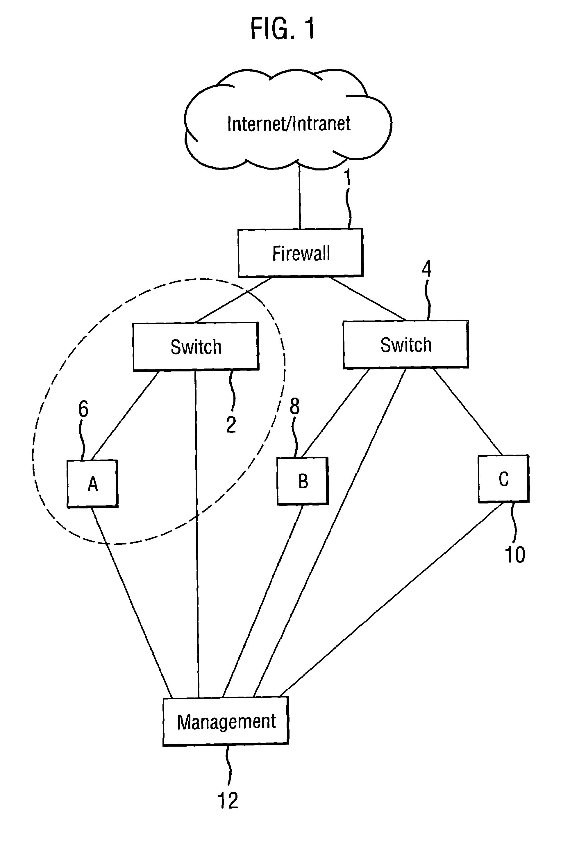
[0042]Referring now to the drawings, in which like reference numerals are used to designate corresponding elements, FIG. 1 shows part of a network in which one or more electronics assemblies according to one embodiment of the present invention may be employed. The network may for example be a local area network, or a wide area network and may be connected to other networks such as the internet. The network may comprise a firewall 1 for connection to the internet, for protecting the network from viruses and unauthorized access, and for load balancing of the network, switches 2 and 4 (there may be many such switches in any one network) and customer servers 6, 8 and 10. Thus, part of the network comprising server 6, part of switch 2 and part of the firewall 1 will form a network of customer A, while other parts of the network will form networks of customers B and C. All these networks will typically be housed in one data centre that is run by a separate management organisation 12 that ...


PUM


Abstract

A computer assembly for example for use as a network server comprises housing a host processor located within the housing and, a service processor also located within the housing for providing system management functions within the computer assembly. The housing includes a display that is located thereon for displaying the status of components of the assembly obtained from the service processor, and one or more manual switches located on the housing for enabling a user to vary information displayed by the display and / or to alter the status of the equipment. The computer assembly may include a console interface that communicates with the service processor to enable the system management functions of the assembly to be monitored and / or the status thereof to be modified from a remote console connected thereto in addition to or instead of by the display and switches.

Description

BACKGROUND OF THE INVENTION[0001]This invention relates to computer assemblies, and especially to computer assemblies that are employed as servers in data networks.[0002]The assemblies may for instance be employed as servers for example in local area networks (LANS) or in wide area networks (WANs), telecommunications systems or other operations such as database management or as internet servers. Such servers may be used in so-called “horizontally scaled” applications in which tens or hundreds of corresponding servers are employed as part of a distributed system.[0003]A typical computer employed for such purposes will comprise a pair of processors mounted on a motherboard, together with power supply units (PSUs), and other components such as hard disc drives (HDDS), fans, digital video disc (DVD) players, memory modules etc. One or more of the processors, the host processor(s), provides the main functions of the server, and may communicate with a number of peripheral components, incl...

Claims


Application Information

Patent Timeline
Patent Type & Authority Patents(United States)
IPC IPC(8): G06F3/00G09G5/08
CPCG06F3/0219
Inventor KING, JAMES EDWARDJONES, RHOD JAMES
Owner ORACLE INT CORP
Why Eureka
Try Eureka