Gage for measuring diameters

a technology of gages and diameters, applied in the field of measuring gages, can solve problems such as measurement differences, and achieve the effect of low heat transfer coefficien

Active Publication Date: 2008-02-12
TECH ALLIANCE INC THE
View PDF9 Cites 11 Cited by
  • Summary
  • Abstract
  • Description
  • Claims
  • Application Information

AI Technical Summary

Benefits of technology

[0010]Preferably drag brakes are mounted in each of the blocks comprising a block set. The drag brakes react against the side rails and bias the juxtaposed blocks toward each other, retarding movement of the arm and block set when the locking fastener is loosened. Each of the block sets is preferably rotatable 180 degrees around the axis of the locking fastener and relative to the side rails without removing its arm or removing the block set from the side rails. This allows the arms and reference planes on the blocks to be rotated from an inside diameter measuring position to an outside diameter measuring position.
[0012]One of the probes comprises a dial indicator for indicating the difference between the specified dimension and the actual measurement. The other probe comprises a contact mounted to a vernier threaded member for precise distance adjustment between probes. Recesses in the block sets allow the indicator probes to be positioned in close proximity to the bottom or reference plane of the block sets for measuring diameters near the end of the workpiece. Preferably an elastomeric or plastic layer is placed on portions of the side rail to serve as a thermal barrier against operator contact. The elastomeric or plastic layer has a low heat transfer coefficient to avoid warmth of the operator's hands from heating the side rails, which could result in differences in measurement.

Problems solved by technology

The elastomeric or plastic layer has a low heat transfer coefficient to avoid warmth of the operator's hands from heating the side rails, which could result in differences in measurement.

Method used


Image

  • Gage for measuring diameters
  • Gage for measuring diameters
  • Gage for measuring diameters

Examples


Embodiment Construction

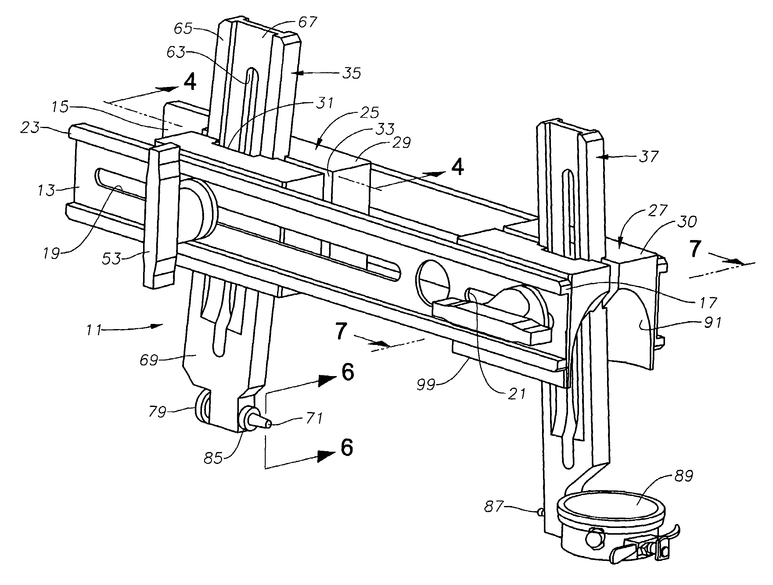
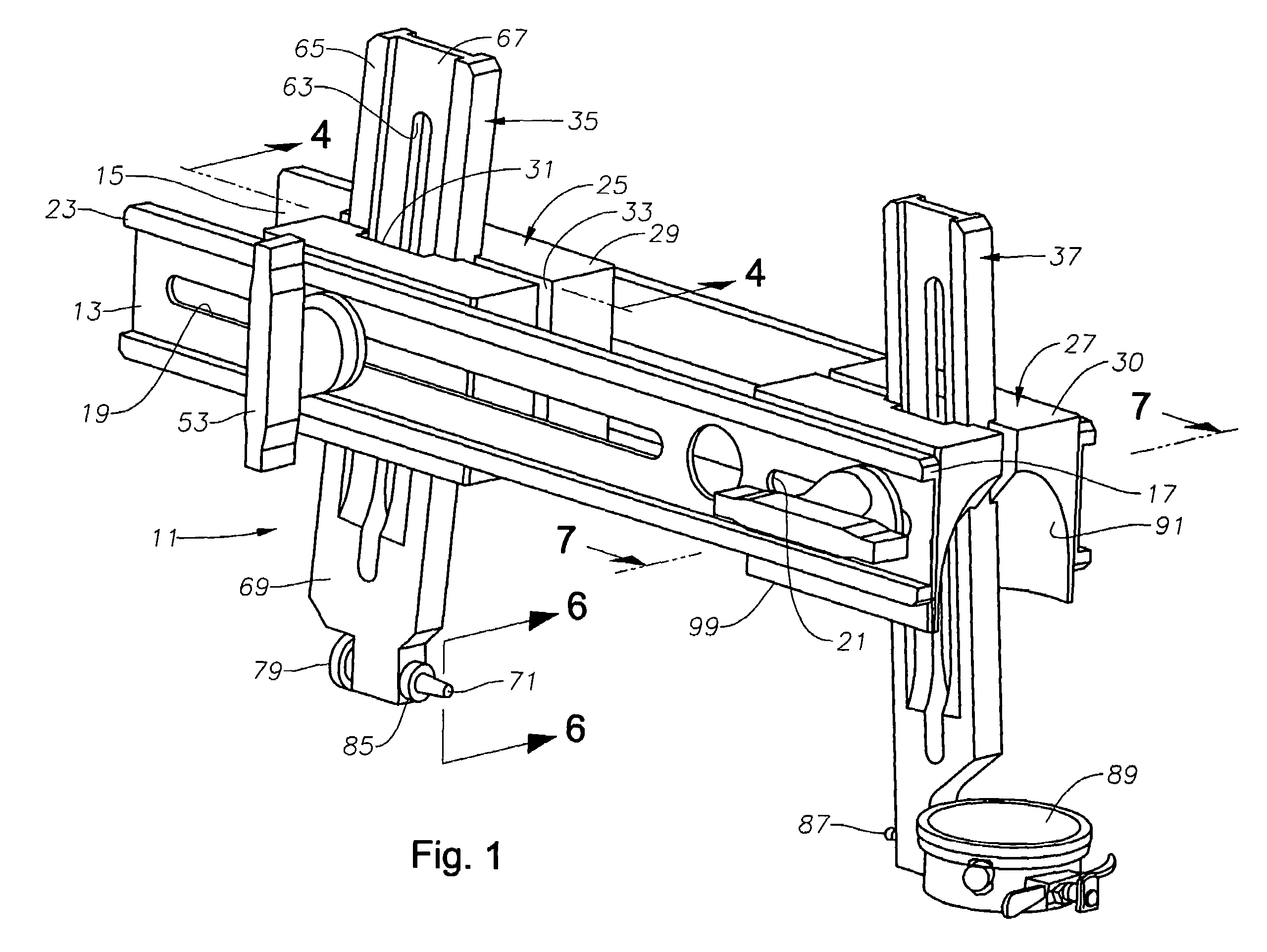
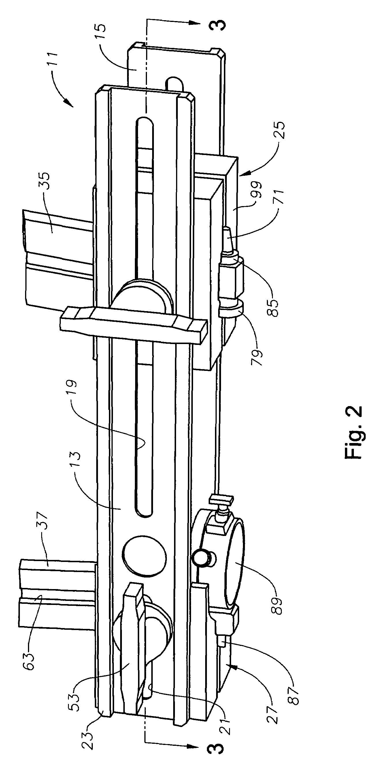
[0020]Referring to FIG. 1, gage 11 has a pair of side rails 13, 15, preferably formed of metal, such as steel. Side rails 13, 15 are mirror images of each other, parallel to each other, and spaced apart from each other. Each side rail 13, 15 is a generally flat rectangular bar with flanges 17 at its upper and lower edges. In cross section as shown in FIGS. 5 and 7, each side rail 13, 15 are in the form of a C-Beam. Each side rail 13, 15 has a width measured from the upper side of one flange 17 to the lower side of its other flange 17 that is greater than its thickness. When gage 11 is oriented as shown in FIG. 1, the width is in a vertical plane.

[0021]Each side rail 13, 15 have a pair of adjusting slots 19, 21. Slots 19, 21 are elongated holes or slots that extend parallel to the length or longitudinal axis of each side rail 13, 15. In this embodiment, slot 19 has a much greater length than slot 21 although they could be the same length. Alternately, slots 19, 21 could be a series o...


PUM


Abstract

A gage for measuring a diameter of a workpiece has a pair of parallel spaced apart side rails. A pair of block sets is mounted between the side rails and spaced apart from each other. A pair of arms extends transverse to the rails through mating profiles in the blocks of each block set. The arms are slidable in a transverse direction to the side rails. Each block set can slide along the side rails and has a single fastener that secures the blocks to the side rails and the arms to the blocks in a desired position. Drag brakes between the blocks and the side rails prevent the components from sliding of their own weight while the fasteners are loosened. The block sets and arms are rotatable 180 degrees about the fasteners when loosened to accommodate outside and inside measurements.

Description

FIELD OF THE INVENTION[0001]This invention relates in general to measuring gages, and in particular to a gage for measuring thread diameters, seal diameters, and other tapered and cylindrical diameters.DESCRIPTION OF THE PRIOR ART[0002]Precision machined parts must be carefully measured to assure that tolerances are met in order for the part to function properly. For example, threaded connectors for offshore oilfield production risers must be machined to close tolerances. For test and qualification purposes even closer tolerances are required. These connectors require accurate measurements at the threads, seal recesses and inner and outer diameters.[0003]A typical measuring gage for these purposes has a frame with two spaced-apart arms mounted to blocks that slide on the frame. The arms slide relative to the blocks in directions transverse to the frame. Probes are mounted to the lower ends of the arms for engaging opposite sides of the work piece. Present measuring gages of this typ...

Claims


Application Information

Patent Timeline
Patent Type & Authority Patents(United States)
IPC IPC(8): G01B5/00
CPCG01B5/08G01B5/12G01B5/204
Inventor GALLE, SR., EDWARD M.
Owner TECH ALLIANCE INC THE
Why Eureka
Try Eureka