Installation for continuously producing a thin steel strip

a technology of continuous production and thin steel, applied in the direction of thin steel strips, etc., can solve the problems of insufficient quality of steel strips, and achieve the effect of producing corresponding steel strips more economically

Inactive Publication Date: 2008-02-12
VOEST ALPINE AG
View PDF19 Cites 14 Cited by
  • Summary
  • Abstract
  • Description
  • Claims
  • Application Information

AI Technical Summary

Benefits of technology

[0008]It is an object of the present invention to avoid these known drawbacks of the prior art and to further develop a process for particular steel grades and an installation for forming metal strip, in such a manner that it is possible to produce a corresponding steel strip more economically.
[0012]The procedure described in the present invention has for the first time made it possible, with the abovementioned composition of the steel melt, to produce a crack-free strip with a good strip profile, in particular a good strip crown. Furthermore, it is possible to achieve a strip temperature across the width of the strip which is more homogenous than in the prior art even just below the permanent mold or casting rolls, in particular within a strip width, of ±25 K. The strip produced using the process according to the invention does not generally have any thermally induced diagonal streaks and is distinguished by a good quality of its edges.
[0016]As tests have shown, this inventive measure makes it possible to produce a particularly high-quality surface of the steel strip.
[0018]As tests have shown, this inventive measure makes it possible to produce a steel strip with particularly high-quality mechanical properties, in particular with an improved toughness.
[0020]In practice, it has been found that this inventive measure makes it possible to realize a particularly high-quality surface, combined at the same time with improved process economics. At lower rates, overflows and the formation of creases in the strip surface (often associated with surface cracks) are observed with increasing regularity.
[0043]Tests have shown that this inventive measure, continuing to take account of the roll separating force RSF, makes it possible to achieve a degree of solidification which is sufficiently uniform over the width of the casting strip, in particular including in the region of the strip edges, and thereby to further increase the efficiency of the proposed process according to the invention.

Problems solved by technology

During the direct casting of non-stainless (Cr and / or Ni content in each case below 1%) liquid steel to form thin strips with a thickness of between 1 and 10 mm, use of the process parameters which are known from the prior art therefore produces a steel strip of inadequate quality.

Method used


Image

  • Installation for continuously producing a thin steel strip
  • Installation for continuously producing a thin steel strip
  • Installation for continuously producing a thin steel strip

Examples


Embodiment Construction

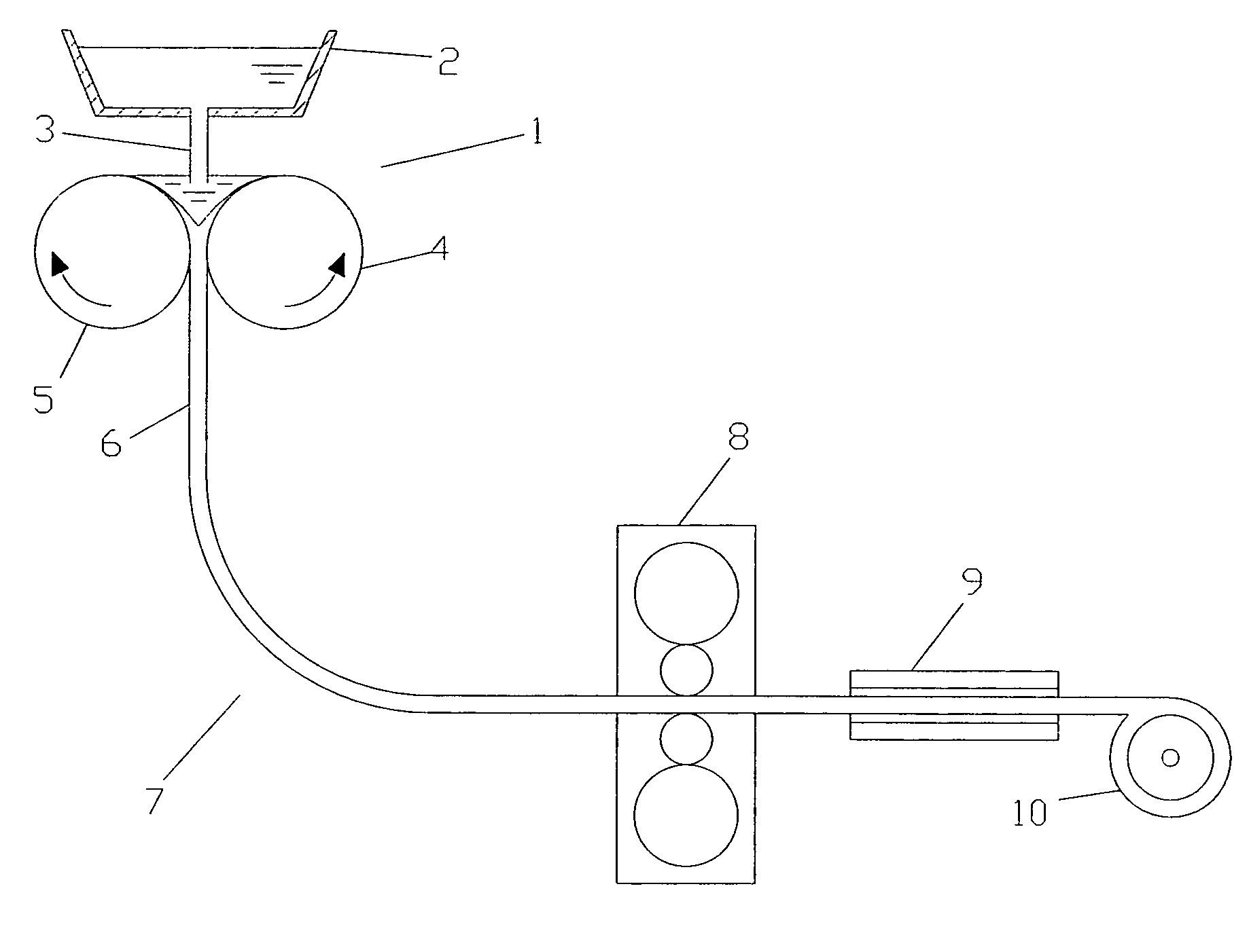
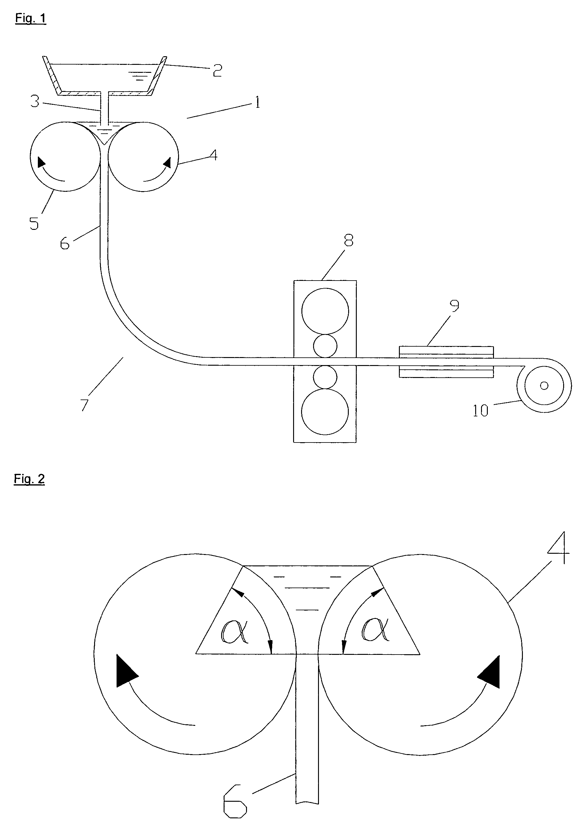
[0095]The casting and rolling apparatus illustrated in FIG. 1 has a strip-casting installation 1 comprising a casting ladle 2 with a casting nozzle 3 and two oppositely rotating casting rolls 4, 5. The casting strip 6 is conveyed via a cooling section 7 to a rolling stand 8.

[0096]In the rolling stand 8, the thickness of the metal strip is reduced by at least 10%. The strip which has been rolled in this way is conveyed through a holding and / or heating device 9 and is coiled at a coiler 10.

[0097]According to a particular embodiment of the invention, the coiled strip is heat-treated in a suitable heat-treatment installation (not shown).

[0098]The definition of the meniscus angle a can be seen from FIG. 2. The meniscus angle a is determined on the basis of a normal section (plane perpendicular to the center axis of the casting roll) between the connection[0099]of the point of contact of the casting level with the outer circumference of the casting roll and the[0100]center point of the ca...


PUM

PropertyMeasurementUnit
thicknessaaaaaaaaaa
thicknessaaaaaaaaaa
diameteraaaaaaaaaa

Abstract

A process for the continuous production of a thin steel strip, in which a steel melt from a melt reservoir is introduced onto one or more, in particular two, cooled shaping wall surfaces which move synchronously with a casting strip, in particular rotate in the form of casting rolls and at least partially solidifies at the shaping wall surface to form the casting strip. The steel melt, in terms of the crucial alloying constituents, contains less than 1% by weight of Ni and less than 1% by weight of Cr and less than 0.8% by weight, in particular less than 0.4% by weight, of C and at least 0.55% by weight of Mn. In the process, recesses are arranged on the shaping wall surface in a random pattern, distributed uniformly over the shaping wall surface, and the roll separating force (RSF) at the shaping wall surface is set to a value of between 5 and 150 N / mm, in particular between 5 and 100 N / mm.

Description

CROSS REFERENCE TO RELATED APPLICATION[0001]The present application is a continuation in part under 35 U.S.C. § 120 of a PCT / EP2003 / 011007 filed 6 Oct. 2003, which claims priority of Austrian Application No. A1561 / 2002 filed 15 Oct. 2002. The PCT International Application was published in the German language.BACKGROUND OF THE INVENTION[0002]The invention relates to a process and to an installation for the continuous production of a thin steel strip. The installation has at least two casting rolls and if appropriate, has laterally arranged side plates. It is possible for a casting reservoir, from which liquid steel melt can be introduced to the casting rolls, to form between the casting rolls and the side plates during operation.[0003]During the production of a steel strip from a steel melt comprising at least the following alloying constituents:[0004]less than 1% by weight of Ni[0005]less than 1% by weight of Cr[0006]less than 0.8% by weight of C, in particular less than 0.4% by wei...

Claims


Application Information

Patent Timeline
Patent Type & Authority Patents(United States)
IPC IPC(8): B22D11/06B22D11/16
CPCB22D11/0622B22D11/0651B22D11/16B22D11/0697B22D11/0674
Inventor HOHENBICHLER, GERALD
Owner VOEST ALPINE AG
Why Eureka
Try Eureka