Clamp tool

a technology of clamping and tooling, which is applied in the direction of clamping, manufacturing tools, and surfaces, to achieve the effects of increasing rigidity, not rotating, and easy attachment and disassembly

Inactive Publication Date: 2008-02-12
OFF CORP
View PDF4 Cites 6 Cited by
  • Summary
  • Abstract
  • Description
  • Claims
  • Application Information

AI Technical Summary

Benefits of technology

[0008]The clamp tool according to the invention includes a pair of clamping brackets and a shaft on which the clamping brackets are slidably disposed. The shaft has a hollow structure in which at least the ends are open in a pipe shape. A pipe made of mainly metal having rigidity, such as a gas pipe, a water pipe, and a scaffolding pipe put on the market, can be used as the shaft. It is preferable that the pair of clamping brackets can slide on the shaft. However, one clamping bracket which is operated by the screw mechanism may be movable and the other clamping bracket may not be movable. If the other clamping bracket is also movable, it can improve manipulability of the clamp tool.
[0010]The male screw is screwed to the female screw on the side of the shaft to move forwardly and backwardly, and a handle for rotationally manipulating the male screw is disposed at one end of the shaft outside the slide cylinder. A guide portion is formed so as not to rotate even when a relative rotational force is applied between the shaft and the slide cylinder by means of a screwing torque of the female screw and the male screw. The guide portion can include a longitudinal hole in the axis direction formed in the slide cylinder and a shaft pin attached to the shaft through the longitudinal hole so that it comes in contact with the side wall of the longitudinal hole to stop the rotation. A bias member such as a coil spring may be disposed between an end of the shaft and an inner end of the slide cylinder so that one clamping bracket is biased in a direction in which it is apart away from the other clamping bracket. In the invention, the constituent components can be easily attached and detached.
[0011]Since the invention has the above-mentioned structure and operates as described above, the screw mechanism is housed in the shaft so as not to be exposed. In addition, since the screw mechanism is disposed on the side of the shaft in one clamping bracket operating with the manipulation of the handle among a pair of clamping brackets, and the clamping bracket acts on a workpiece to be clamped similarly to the other clamping bracket, the workpiece can be interposed between both the clamping brackets in the substantially same method without leaning on any one. In addition, since the so-called arm dimension becomes smaller, the entire rigidity is increased, thereby interposing the workpiece with accurate balance.

Problems solved by technology

However, one clamping bracket which is operated by the screw mechanism may be movable and the other clamping bracket may not be movable.

Method used


Image

  • Clamp tool
  • Clamp tool
  • Clamp tool

Examples


Embodiment Construction

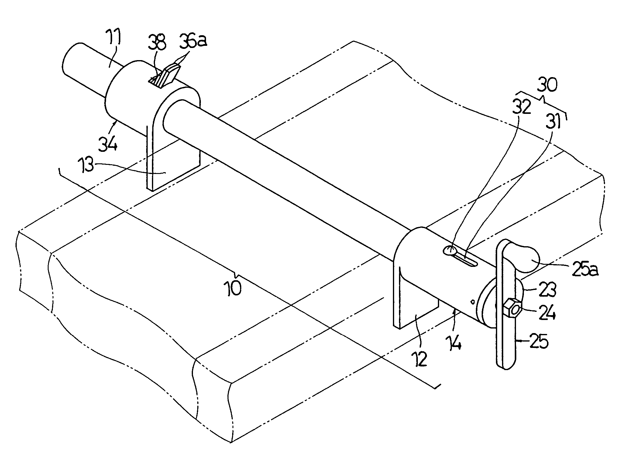
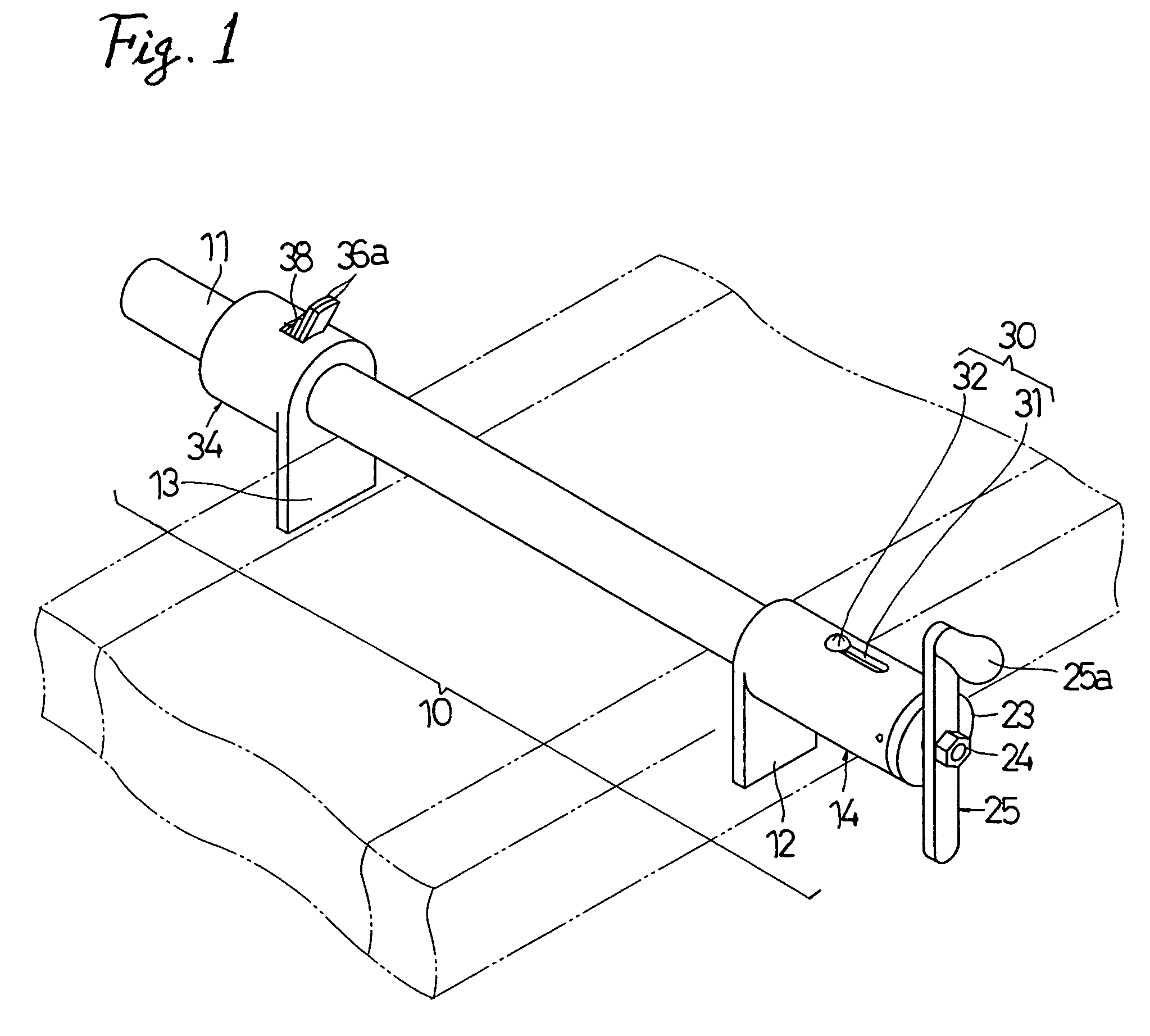
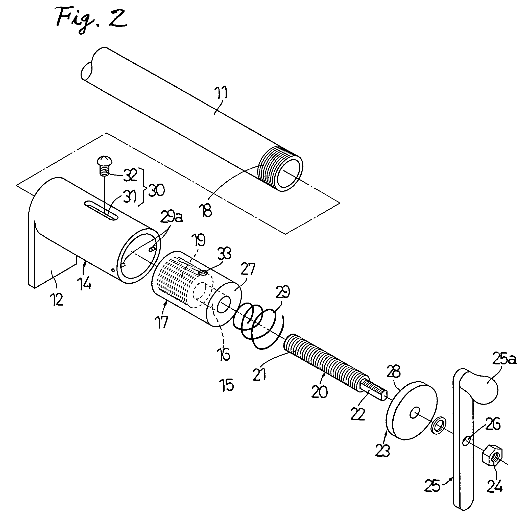
[0018]Hereinafter, the invention will be described in detail with reference to embodiments illustrated in the drawings. FIG. 1 illustrates an example of a clamp tool 10 according to the invention, where the clamp tool includes a shaft 11 and a pair of clamping brackets 12 and 13 disposed on the shaft apart from each other. The shaft 11 has a pipe structure as a rigid body and uses a rigid pipe such as a gas pipe, a water pipe, and a scaffolding pipe as described above. Accordingly, the length of the shaft 11 can be determined as needed, and the entire inside thereof is hollow.

[0019]One clamping bracket 12 is formed integrally with a slide cylinder 14 fitted to the outside of the shaft 11 and the slide cylinder 14 is movable along the shaft 11 using a screw mechanism 15. Accordingly, an end member 17 having a female screw 16 constituting a screw mechanism 15 is attached to an end of the shaft 11. Reference numerals 18 and 19 denote screwing portions for attaching the end member 17 to...


PUM


Abstract

A clamp tool for woodwork or metalwork in which a screw mechanism is not apart away from a shaft and is not exposed is disclosed. In the clamp tool, a pair of clamping brackets is disposed on a shaft apart from each other and at least one clamping bracket is movable along the shaft to fasten a workpiece in cooperation with the other clamping bracket. Here, a female screw constituting a screw mechanism is disposed at one end of the shaft, a male screw constituting the screw mechanism is rotatable in a slide cylinder disposed outside at the end of the shaft so as to be screwed to the female screw, a handle for rotationally manipulating the male screw is disposed, and a guide portion is disposed between the shaft and the slide cylinder so that the female screw does not rotate but goes straight with the rotation of the male screw so as to allow the clamping bracket disposed outside the slide cylinder to move along the shaft.

Description

BACKGROUND OF THE INVENTION[0001]1. Technical Field[0002]The present invention relates to a clamp tool in which a pair of clamping brackets is disposed on a shaft apart from each other, at least one clamping bracket can move along the shaft to fasten a workpiece in cooperation with the other clamping bracket.[0003]2. Related Art[0004]Such a kind of manual tool is used for coupling wood blocks to each other. For examples, U.S. Pat. No. 4,552,345 discloses a structure which includes a pair of clamping blocks disposed along a shaft, in which one clamping block moves toward the other clamping block to fasten a plurality of workpieces interposed between the pair of clamping blocks and a member for supporting the workpieces so as not to bow due to the fastening force. This structure is a typical example. On the other hand, a clamp is also known in which a pair of clamping brackets is formed to move or stop on a pipe-shaped shaft, one clamping bracket is movable with a screw mechanism, and...

Claims


Application Information

Patent Timeline
Patent Type & Authority Patents(United States)
IPC IPC(8): B25B1/02
CPCB25B1/103B25B1/125B25B5/10B25B5/102
Inventor WATANABE, SHUNSUKEYOSHIDA, MASARU
Owner OFF CORP
Why Eureka
Try Eureka