Sectional interlocking barrier bags

a sectional interlocking and barrier bag technology, applied in the field of bags, can solve the problems of difficult to keep stacked sandbags, lack of stable structure, and inefficient methods, and achieve the effects of reducing the number of bags

Inactive Publication Date: 2008-02-12
SLATER +1
View PDF21 Cites 27 Cited by
  • Summary
  • Abstract
  • Description
  • Claims
  • Application Information

AI Technical Summary

Benefits of technology

[0005]Applicants' invention comprises a length of material, such as canvas, woven polyethylene, woven polypropylene, burlap, ballistic nylon, woven organic fibers or other material, divided into a unit having a series of two or more substantially equal sized sections. Every other section is filled with particulate, such as sand, or other equivalent material, and every unit has an unfilled end-flap at both ends. When multiple sections are put in place, each row with an alternating filled section and an unfilled section, and stacked in layers, there is created a very secure, substantially water-tight structure. Because each section is substantially square, the sections can be stacked in a parallel or transverse direction, to effect a wider and stronger water-fight structure. The sections interlock to attain greater strength and water flow prevention. By having an unfilled section at both ends of each unit, the bag units are reversible or bi-directional. That is, they may be stacked in any direction, parallel or transverse, in either direction, and no time needs to be spent in making sure they are stacked correctly.
[0006]In addition, there is a great need for a field-fillable bag, that is, a bag that is not filled with sand, or other material, until it is used in the field. Applicants have provided an improved bag which is easily and quickly fillable in the field and easily and quickly sealed after it has been filled.

Problems solved by technology

Sandbags now in use are difficult to keep stacked, and they do not provide a stable structure when stacked or piled.
However, as can be clearly seen, there are gaping spaces between the stacked bags, allowing considerable water to pass through the stacked bags.
This method is very inefficient because the protuberances do not maintain their integrity on site.
These fillers can get easily clogged and the bags can get easily misshapen so that they do not fit together.

Method used


Image

  • Sectional interlocking barrier bags
  • Sectional interlocking barrier bags
  • Sectional interlocking barrier bags

Examples


Embodiment Construction

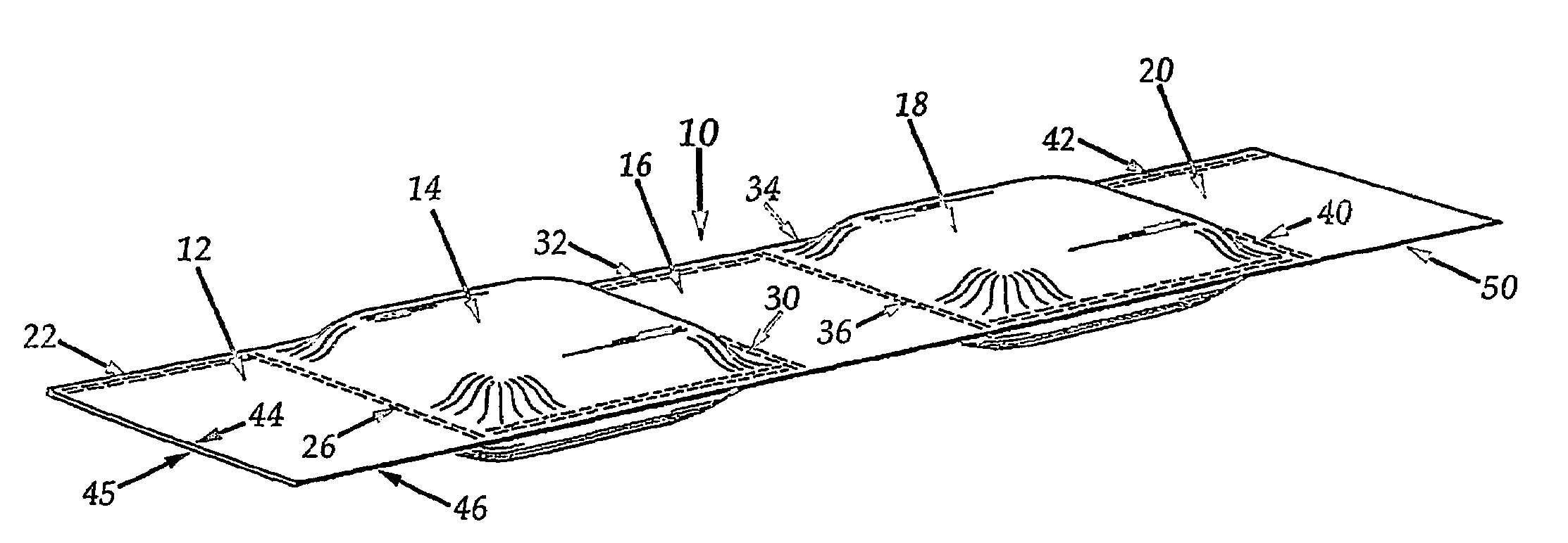
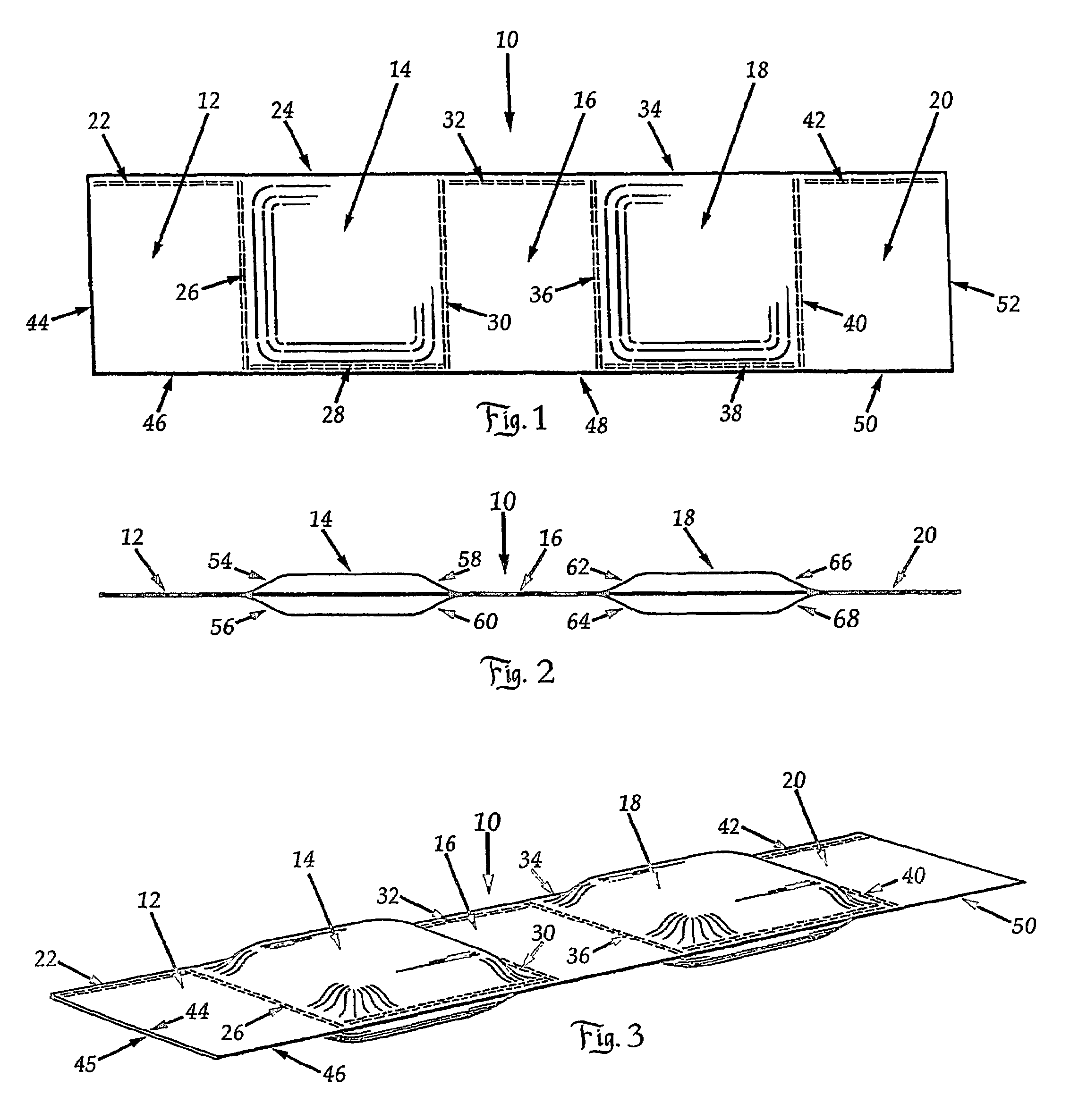
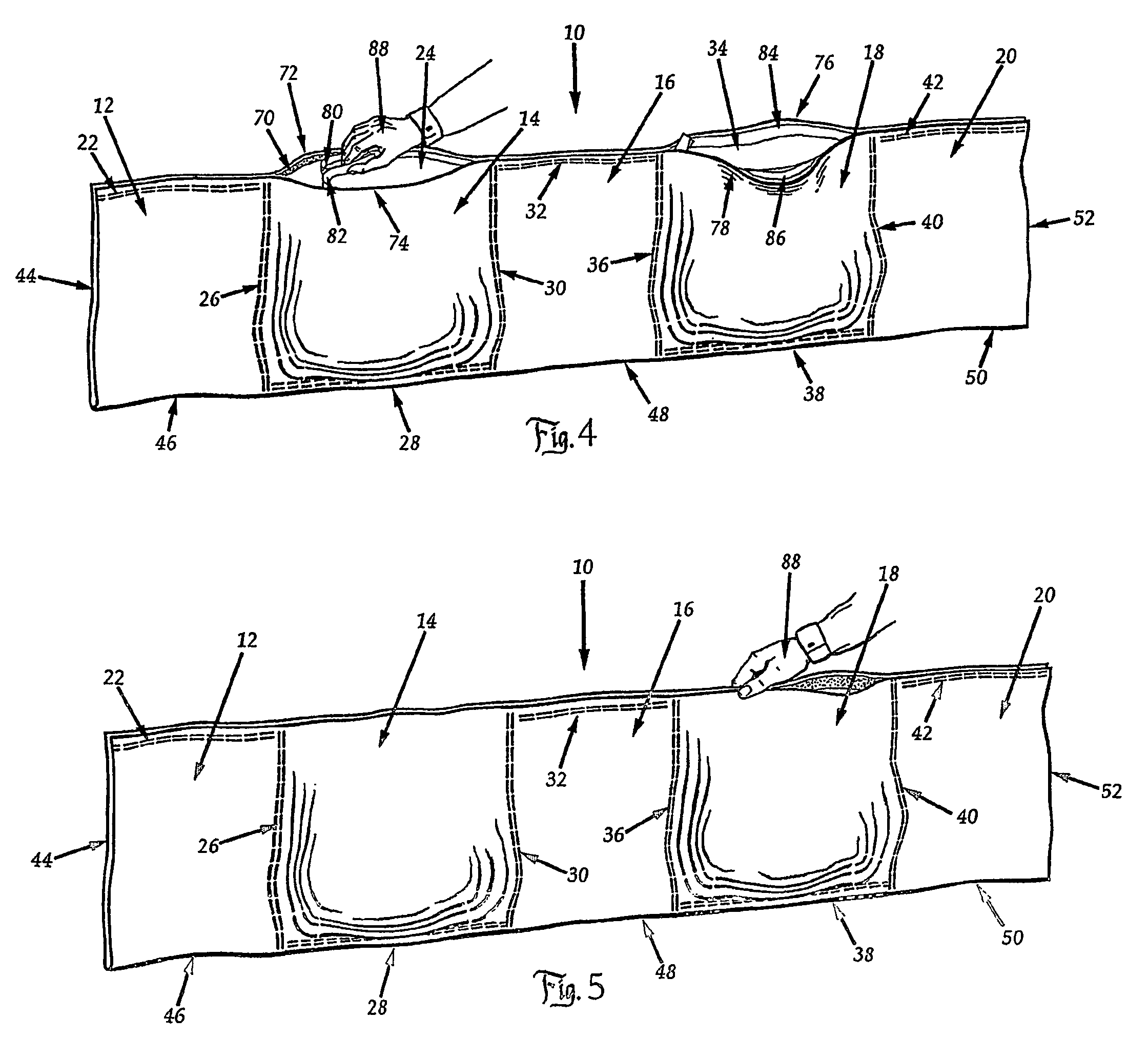
[0014]Referring now to the drawings, there is shown in FIGS. 1-3 a length of material 10, such as canvas, woven polyethylene, woven polypropylene, burlap, ballistic nylon, woven organic fibers or other material, formed into a single bag unit by folding over the material 10 lengthwise into two equal-sized lengths and dividing the folded material into substantially equal-sized, square sections 12, 14, 16, 18 and 20. Sections 14 and 18 are filled with sand, or another material, and sections 12, 16 and 20 are unfilled. The sections are divided and sealed along dotted lines 22, 24, 26, 28, 30, 32, 34, 36, 38, 40 and 42, by any method of sealing the sections apart, such as heat, sewing, clamping, stapling or adhesive. Since material 10 is folded over lengthwise, there is no need to seal the material at edges 44, 46, 48, 50 and 52. However, if desired, these edges can also be sealed by any of the same methods. FIG. 3 shows the material 10 folded over into two equal lengthwise portions at e...


PUM


Abstract

A bag made from a length of material (10) divided into a series of three or more substantially equal sized sections (12, 14, 16, 18, 20). Every other section is filled with sand (14, 18), or other particulate material and there is an unfilled section (12, 20) at each end.

Description

TECHNICAL FIELD[0001]The invention relates to bags used to provide a barrier. The barrier may prevent the passage of liquid, water, mud and silt during a flood or for other fluid flow problems. The barrier may also be used to protect against the collapse of dry sand or earth for below-grade retaining walls and trenching, or for the purpose of protection from gunfire explosive blasts and shrapnel, etc. in military applications.BACKGROUND ART[0002]The invention described herein has improvements over the bag system described in our issued U.S. Pat. No. 6,428,240. The improvements are discussed below.[0003]Sandbags now in use are difficult to keep stacked, and they do not provide a stable structure when stacked or piled. Suggestions have been made to provide a method for stacking bags, such as in U.S. Pat. No. 3,374,635 where rounded bags are tied together with lashing. However, as can be clearly seen, there are gaping spaces between the stacked bags, allowing considerable water to pass...

Claims


Application Information

Patent Timeline
Patent Type & Authority Patents(United States)
IPC IPC(8): E02B7/00E02B3/10E02B3/12F42D5/045
CPCE02B3/108F42D5/05F42D5/045E02B3/127
Inventor SLATER, STEVE A.EHRLICH, PETER D.
Owner SLATER
Why Eureka
Try Eureka