Damping element

a technology of pedicle screws and components, applied in the field of pedicle screws, can solve the problems of affecting the operation, affecting the operation, and affecting the operation,

Inactive Publication Date: 2008-02-12
SYNTHES USA
View PDF18 Cites 200 Cited by
  • Summary
  • Abstract
  • Description
  • Claims
  • Application Information

AI Technical Summary

Benefits of technology

[0014]after traction has been applied to the vertebras, the damping elements may be inserted in quick and simple manner between the pedicle screws and then be affixed to them.
[0015]In one embodiment of the damping element of the invention, the spring elements are designed to exhibit a constant spring rate. As a result, the unloaded spring elements' states may be restored after the damping element has been relieved.
[0016]In another embodiment of the damping element of the invention, its cross-section orthogonal to the longitudinal axis is reniform. Such a design offers the advantages that when implanting one or several damping elements, for instance in the process of spinal column fixation, said elements may be positioned more advantageously with respect to vertebral extensions or other implant components.
[0020]Pedicle screws or pedicle hooks that are fitted with receiving means allowing concurrent connection between two parallel, longitudinal affixation elements and the pedicle screw or pedicle hook are known for instance from U.S. Pat. No. 4,653,481 (Howland). Similarly to the longitudinal supports cited in said patent, the damping elements of the present invention may be affixed by means of bars mounted on the connectors parallel to the longitudinal axis for instance in parallel ducts to the screw heads. Very easily and without further manipulation, the damping element displaceability in the ducts parallel to the longitudinal axis allows inserting a damping element of the present invention—which was prestressed to a desired spring force before implantation—into the receiving means at the pedicle screws. The compensation in length at different spacings between the pedicle screws or pedicle hooks is implemented by the axial displaceability of the bar-shaped connectors which are configured end-wise parallel to the longitudinal axis and which are situated at the damping elements of the invention in the ducts that are also parallel to the longitudinal axis.
[0021]Illustratively prestressing the damping element allows taking into account a number of instabilities, indications or patient weight. In the case of extension of the pertinent spinal segments, the damping element is compressed, whereas in the case of flexion of the pertinent spinal segment it is tensioned. The selections of the spring material, for instance a polymer, preferably a polycarbonate urethane (PCU) for the compressively loaded spring, and of metal for the tensively loaded spring element, of the geometric dimensions as well as the prestressing of the tensively loaded spring element allow optimally matching the system of the present invention to a patient's biomechanical particulars.

Problems solved by technology

While the length of the spiral springs is adjustable, this design only allows a change in the spring force between two adjacent pedicle screws and hence between two adjacent vertebras.
This system entails the drawback that only compressive forces between the pedicle screws may be absorbed.
Such a design is awkward and entails storing a significant number of damping elements of different lengths.
In the first place the plastic band and the bracing elements must be threaded into or between the boreholes of the pedicle screws which already have been implanted, entailing complexity and loss of time for the surgeon.
This is a complex and time-consuming procedure for the surgeon and might in general result in too short a bracing element, as a result of which its damping would be effective only after a given delay—this circumstance manifestly being undesirable.

Method used


Image

  • Damping element
  • Damping element
  • Damping element

Examples


Embodiment Construction

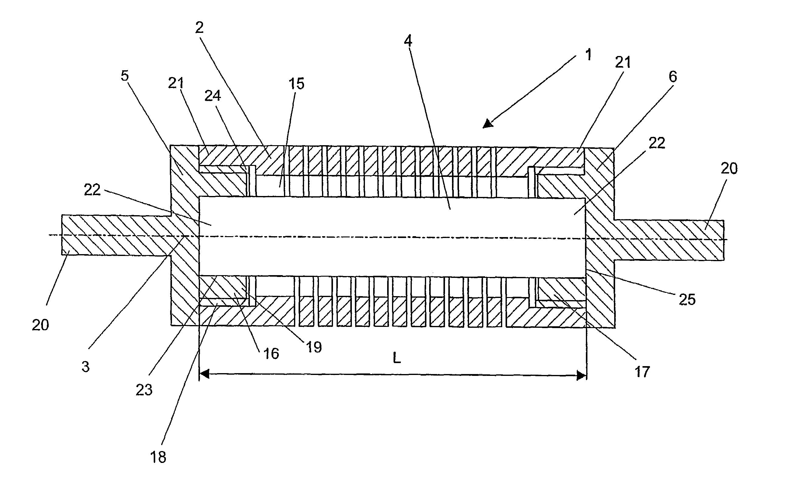
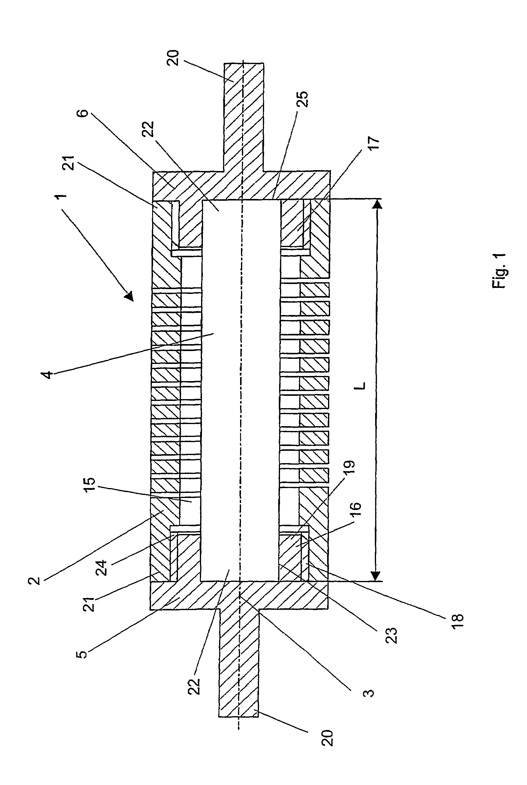
[0032]FIG. 1 shows an embodiment mode of the damping element 1 of the invention having two spring elements 2, 4 concentrically mounted with the longitudinal axis 3. The first spring element 2 is designed as a helical spring with a central cavity 15, whereas the second spring element 4 is bar-shaped and configured in said cavity 15. The end-side connectors 5, 6 also are mounted coaxially with the longitudinal axis 3 and each is fitted with a threaded segment 16, 17 with an outer thread 18, said segments being coaxial with the longitudinal axis 3 and pointing toward the spring elements 2, 4. The first spring element 2 is fitted at its axial ends 21 with inner threads 24 in the cavity 15 which match the outer threads 18, as a result of which the threaded segments of the connectors 5, 6 can be screwed into the first spring element 2. Moreover each connector 5, 6 comprises an open recess 23 configured coaxially with the longitudinal axis 3 at the inner end 19 of said connector, as a resu...


PUM


Abstract

A damping element (1) comprising (a) two spring elements (2, 4) which are coaxial with or parallel to a longitudinal axis (3) and two axially end-wise connectors (5, 6) which can be linked to the spring elements (2, 4), where (b) the first spring element (2) exhibits a spring rate F, (c) the second spring element (4) exhibits a spring rate f, and (d) the spring rates F and f are different. A system stabilizing adjacent vertebras includes: (a) N pedicle screws or pedicle hooks (12), with N≧3, and (b) at least one pedicle screw or one pedicle hook having a receiving device (13) which simultaneously allow receiving two parallel affixation devices (7), and where (c) an element (14) acting as a spring is used for affixation between the minimum of one pedicle screw or pedicle hook (12) including a receiving device (13) and a further adjacent pedicle screw or pedicle hook (12).

Description

CROSS REFERENCE TO RELATED APPLICATION[0001]This is a national stage of PCT International Application No. PCT / CH01 / 00705, filed Dec. 7, 2001.FIELD OF THE INVENTION[0002]The present invention relates to a damping element as defined in the preamble of claim 1 and to a system stabilizing adjacent vertebras as defined in the preamble of claim 15.BACKGROUND OF THE INVENTION[0003]The French patent document FR-A-2,799,949 discloses a spinal fixing system consisting of a number of tulip-like pedicle screws which in lieu of the conventional rigid longitudinal support are connected to each other by spiral spring elements. While the length of the spiral springs is adjustable, this design only allows a change in the spring force between two adjacent pedicle screws and hence between two adjacent vertebras. This document allows no conclusion whether the spring elements are mounted prestressed between the pedicle screws.[0004]Another spinal fixation system is known from the European patent documen...

Claims


Application Information

Patent Timeline
Patent Type & Authority Patents(United States)
IPC IPC(8): A61B17/56A61F2/30F16F3/02A61B17/58A61B17/70F16F1/12F16F3/10
CPCA61B17/7028F16F1/123F16F3/10A61B17/7004A61B17/70
Inventor STUDER, ARMIN
Owner SYNTHES USA
Why Eureka
Try Eureka