Methods of implanting a mitral valve annuloplasty ring to correct mitral regurgitation

a technology of annuloplasty and mitral valve, which is applied in the field of medical devices, can solve the problems of increasing the incidence of mitral valve regurgitation, increasing the area of regurgitant orifice, and rings that are not suitable for correcting bicuspid valve deficiency, and achieves the effect of mitigating the effects of congestive heart failur

Active Publication Date: 2008-02-12
EDWARDS LIFESCIENCES CORP
View PDF21 Cites 266 Cited by
  • Summary
  • Abstract
  • Description
  • Claims
  • Application Information

AI Technical Summary

Benefits of technology

[0012]The present invention provides a number of annuloplasty rings for implantation in a mitral valve annulus that correct both the annulus and help mitigate the effects of congestive heart failure. In one aspect, the invention provides an annuloplasty ring that has a generally oval-shaped ring body defining an anterior portion, a posterior portion opposite the anterior portion, right and left sides between the anterior and posterior portions, and transition segments between the sides and the posterior portion. The ring body is oriented about a central axis having an upward direction and a downward direction, the downward direction corresponding to the direction of blood flow through the mitral valve annulus. The ring has, in plan view perpendicular to the central axis, a longer dimension along a major axis than a shorter dimension along a minor axis, and the posterior portion rises upward from the adjacent transition segments to an axial position higher than the highest axial position of the anterior portion.

Problems solved by technology

Congestive heart failure (CHF) is a leading cause of hospitalization and death in the United States, and its incidence is increasing.
While heart transplantation is considered a standard treatment for select patients with severe CHF and end-stage heart disease, it is only applicable to a small percentage of patients because of the small number of available donor hearts and surgical risks for weaker patients.
An increase in preload or afterload, or a decrease in contractility, results in dilation of the LV and an increase in regurgitant orifice area.
Such rings would not be suitable for correcting a bicuspid valve deficiency.

Method used


Image

  • Methods of implanting a mitral valve annuloplasty ring to correct mitral regurgitation
  • Methods of implanting a mitral valve annuloplasty ring to correct mitral regurgitation
  • Methods of implanting a mitral valve annuloplasty ring to correct mitral regurgitation

Examples


Embodiment Construction

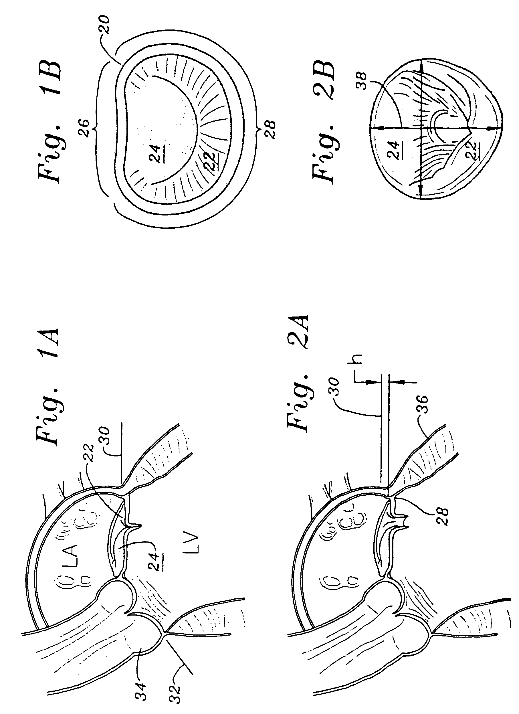
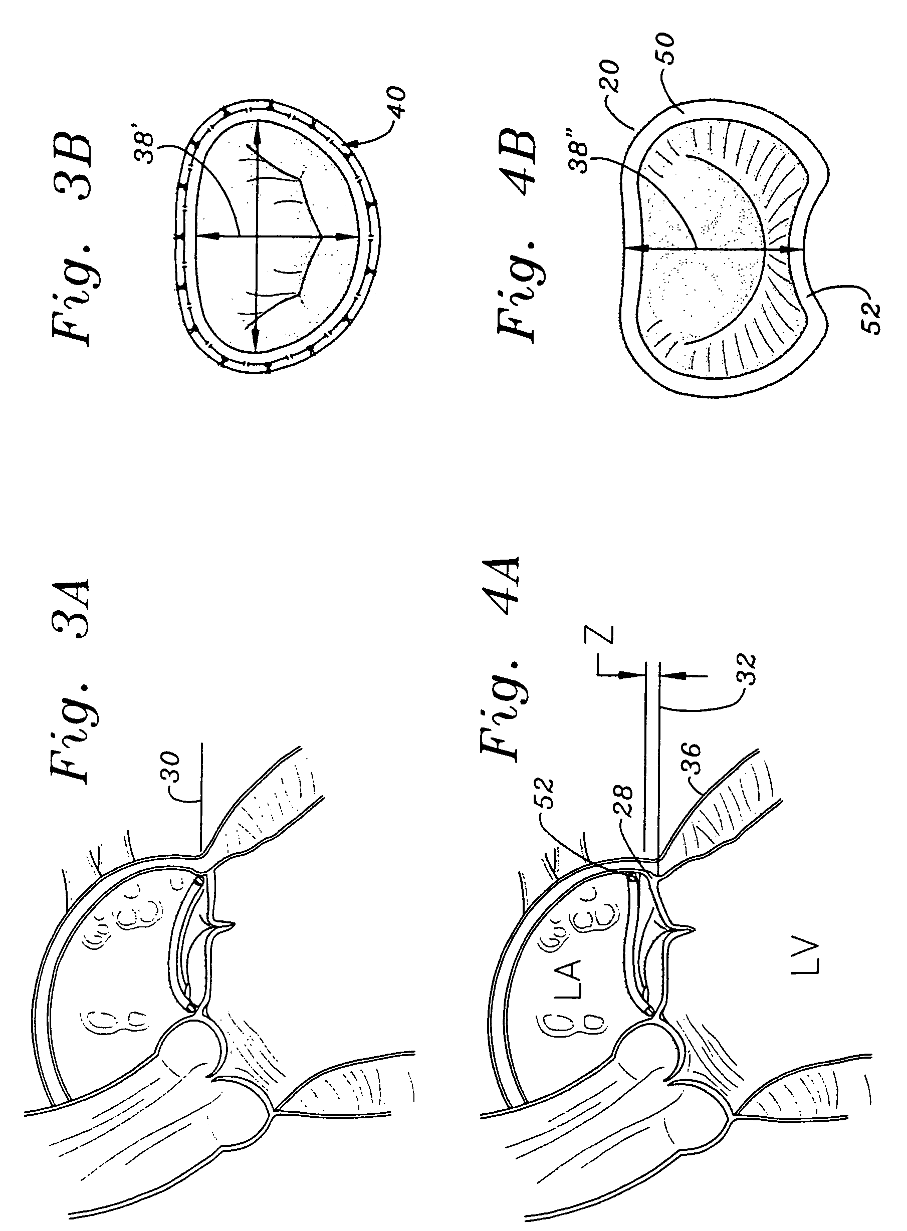
[0033]Applicant has determined that congestive heart failure (CHF) and secondary mitral regurgitation (MR) can be addressed with a new generation mitral annuloplasty ring. The ring when implanted not only modifies the circumference of the mitral annulus as do existing annuloplasty rings, but it also elevates and / or reconfigures the posterior portion of the mitral annulus so as to mold and re-shape the geometry of the left ventricle.

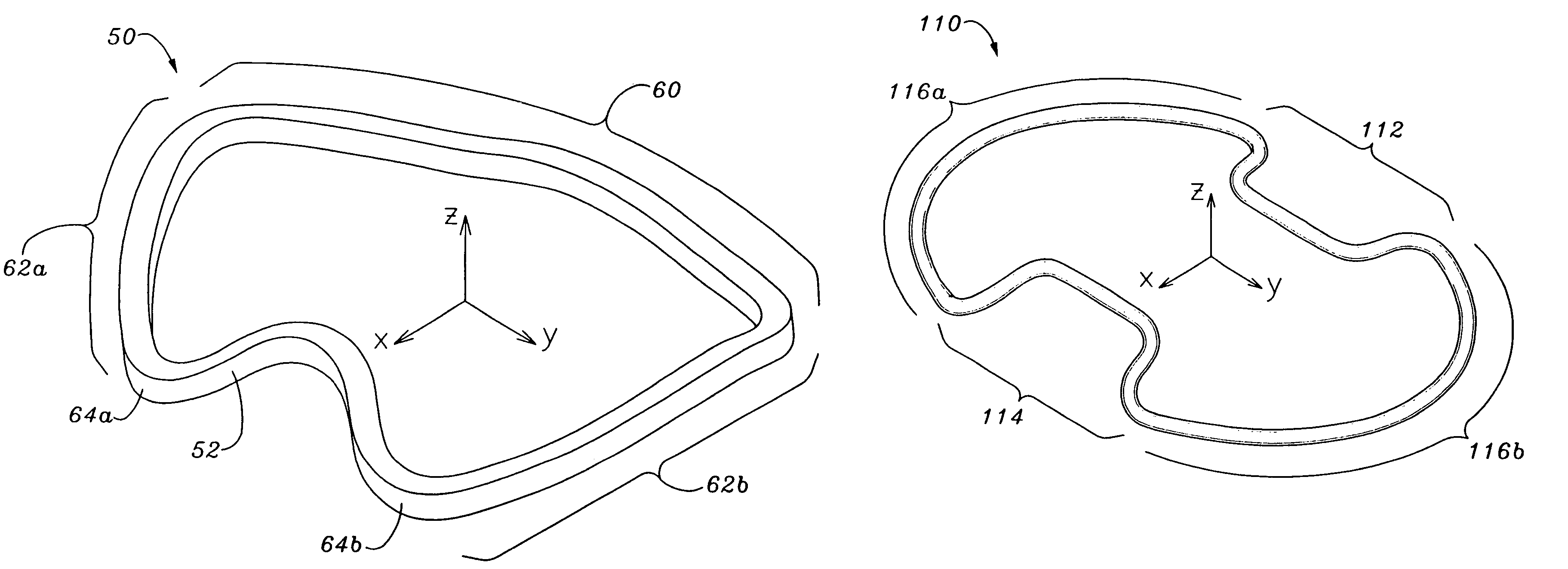
[0034]The attached figures illustrate several exemplary embodiments of the annuloplasty ring of the present invention, which can be described as being continuous and having an anterior side, a posterior side and right and left sides. All of the sides are generally curvilinear with no specific demarcations to indicate abrupt transitions therebetween. Rather, smooth transitional sections between the adjacent sides provide curvilinear connections that give the ring a generally rounded (i.e., oval) configuration.

[0035]With reference to FIGS. 4A and 4B, a firs...


PUM


Abstract

Methods of implanting an annuloplasty ring to correct maladies of the mitral annulus that not only reshapes the annulus but also reconfigures the adjacent left ventricular muscle wall. A posterior portion of the ring rises or bows upward from adjacent sides to pull the posterior aspect of the native annulus farther up than its original, healthy shape. In doing so, the ring also pulls the ventricular wall upward which helps mitigate some of the effects of congestive heart failure. Further, one or both of the posterior and anterior portions of the ring may also bow inward. The methods include securing the annuloplasty ring with the anterior portion against the annulus anterior aspect and the posterior portion against the annulus posterior aspect so that the ring posterior portion elevates, and may also pull radially inward, the annulus posterior aspect and corrects the mitral regurgitation.

Description

RELATED PATENT APPLICATION(S)[0001]The present application is a continuation of U.S. application Ser. No. 10 / 267,272, filed Oct. 9, 2002, now U.S. Pat. No. 6,805,710 which claims priority under 35 U.S.C. §119(e) from Provisional Patent Application No. 60 / 332,353, filed Nov. 13, 2001, both entitled “Mitral Valve Annuloplasty Ring for Molding Left Ventricle Geometry,” the disclosures of which are incorporated by reference herein in their entireties.FIELD OF THE INVENTION[0002]The present invention relates generally to medical devices, specifically to an annuloplasty ring and related procedure for surgically reconstructing and molding the mitral valve annulus of a patient's heart. More specifically, this invention relates to a mitral valve repair device and corresponding technique that involve over-correcting defects in the mitral valve annulus so as to remodel the left-ventricular geometric relationship.BACKGROUND OF THE INVENTION[0003]Congestive heart failure (CHF) is a leading cause...

Claims


Application Information

Patent Timeline
Patent Type & Authority Patents(United States)
IPC IPC(8): A61F2/24
CPCA61F2/2445A61F2/2448
Inventor BOLLING, STEVEN F.RHEE, RICHARD S.
Owner EDWARDS LIFESCIENCES CORP
Why Eureka
Try Eureka