
Transceiver for bidirectional frequency division multiplexed transmission

a multi-frequency division, transmission technology, applied in the direction of pulse combined modulation, simultaneous amplitude and angle demodulation, pulse technique, etc., can solve the problem of reducing the power requirement of transmitting signals, undesirable additional attenuation of receiving signals, and undesired interferen

Inactive Publication Date: 2008-02-12
AVAGO TECH INT SALES PTE LTD
View PDF8 Cites 18 Cited by
  • Summary
  • Abstract
  • Description
  • Claims
  • Application Information

AI Technical Summary

Benefits of technology

The present invention is about a transceiver that can transmit and receive data. The invention has a coupling impedance that is smaller in the transmission frequency range than in the receiving frequency range. This means that the impedance is designed to allow more data to be transmitted than received. The coupling impedance can be a single passive electric element or a combination of several passive electric elements. In one embodiment, the impedance is designed to match the complex conjugate of the transmission medium impedance in the receiving frequency range. In another embodiment, the coupling impedance has a high pass filter characteristic in the transmission frequency range and a low pass filter characteristic in the receiving frequency range. The invention can be used in a communication system for a digital subscriber line. The technical effects of the invention include improved data transmission and reduced interference between data transmission and reception.

Problems solved by technology

For transmitting, however, these impedances are undesired because they imply that more signal power has to be delivered by the transmission means.
This reduces the transmitting signal power requirement but also causes an undesirable additional attenuation of the receiving signals.
This approach also has significant drawbacks.
If, for instance, the impedance of the transmission medium increases the required signal output of the operational amplifiers also increases which can cause undesirable signal clipping or may require increasing the supply voltage of the operational amplifiers.
Increased supply voltage, however, causes additional undesirable power dissipation.
Another disadvantage of this method is that it uses positive feedback, which makes it inherently more prone to oscillations.

Method used


Image

  • Transceiver for bidirectional frequency division multiplexed transmission
  • Transceiver for bidirectional frequency division multiplexed transmission
  • Transceiver for bidirectional frequency division multiplexed transmission

Examples


Embodiment Construction

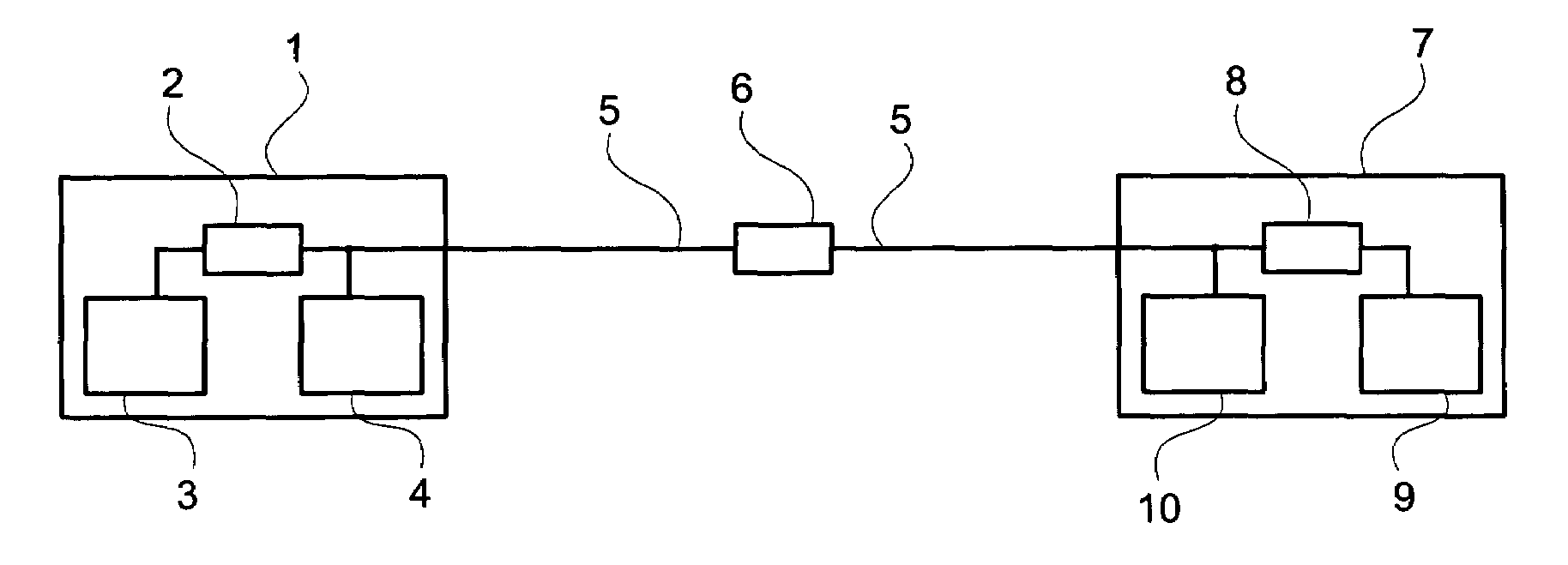
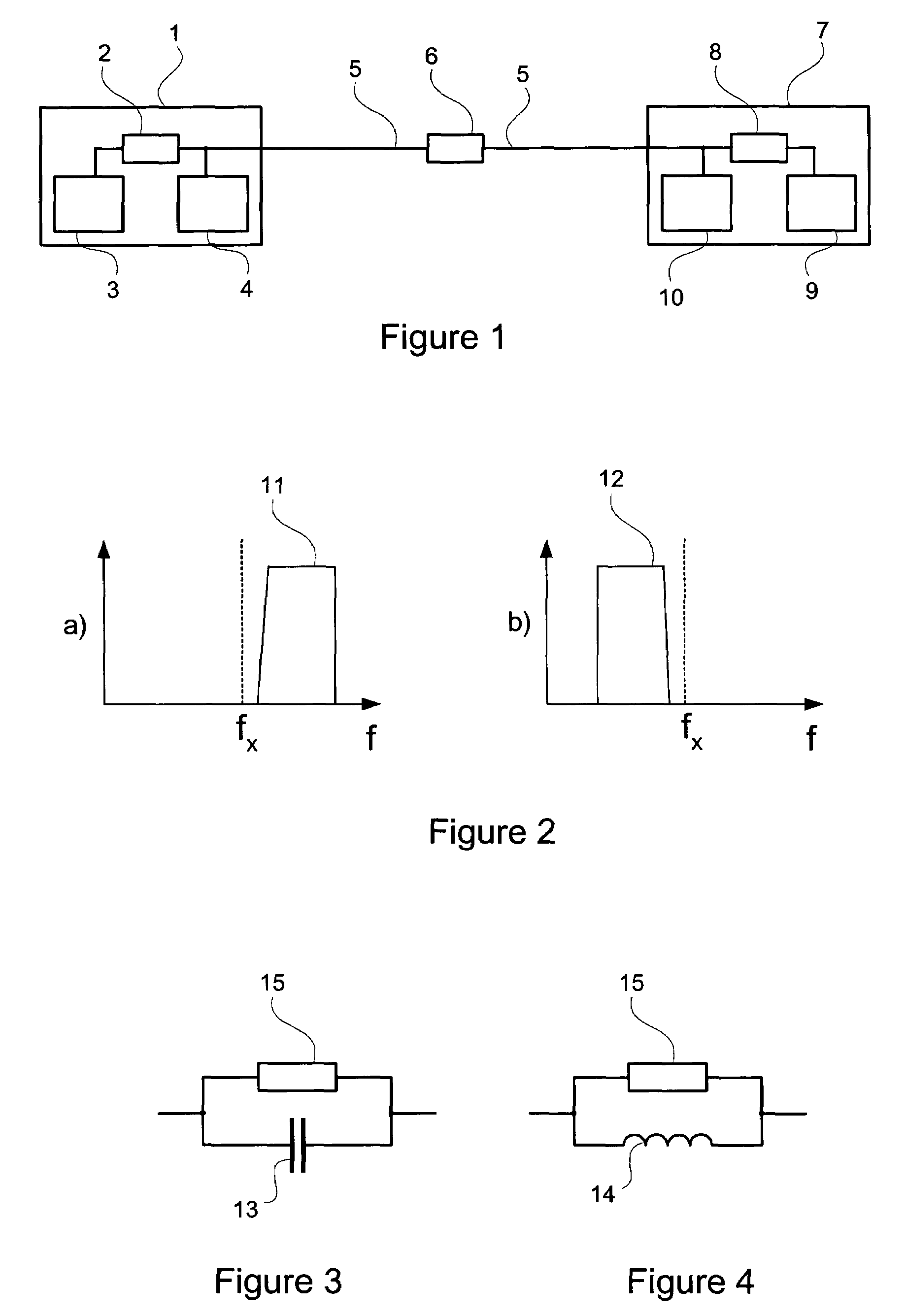
[0020]FIG. 1 illustrates a schematic block diagram of a bidirectional full duplex frequency division multiplexed communication system with a first transceiver 1 and a second transceiver 7, both transceivers 1, 7 being connected together by means of a transmission line 5. The impedance of the transmission line 5 is represented by a transmission line impedance 6.

[0021]In a full duplex frequency division multiplexed transmission system, data are transmitted in both directions over a transmission medium. For the simultaneous transmissions of signals in different directions, different frequencies or frequency ranges are used to avoid interference between the two signals. A transceiver for such a communication system is adapted to transmit in a transmitting frequency range and to receive in a different receiving frequency range. The frequency ranges can comprise one single frequency or several different frequencies. Generally the frequency ranges for transmitting or receiving correspond t...


PUM


Abstract

The present invention relates to a transceiver for bidirectional frequency division multiplexed transmission, a communication system including one or more transceivers. Optionally, the communication system is a communication system for a digital subscriber line. The transceiver comprises transmission means with a voltage source output or a current source output for transmitting data in a transmission frequency range, receiving means for receiving data in a receiving frequency range, and a coupling impedance for connecting the transmission means and the receiving means to a transmission medium. The magnitude of the coupling impedance in the transmission frequency range is smaller than the magnitude of the coupling impedance in the receiving frequency range if the transmission means has a voltage source output and is higher than the magnitude of the coupling impedance in the receiving frequency range if the transmission means has a current source output.

Description

CROSS-REFERENCE TO RELATED APPLICATIONS / INCORPORATION BY REFERENCE[0001]This application is related to, and claims benefit of and priority from, Provisional Application No. 60 / 482,494 filed on Jun. 26, 2003, entitled “Optimal Transmitter Topology for Bidirectional Frequency Division Multiplexed”, the complete subject matter of which is incorporated herein by reference in its entirety as if fully set forth herein.BACKGROUND OF THE INVENTION[0002]The present invention generally relates to communication systems for full duplex frequency division multiplexed transmission. The present invention relates more particularly to a transceiver, a communication system using a transceiver, and methods related thereto and used therewith.[0003]Traditionally the coupling impedances are matched to the impedance of a transmission medium in order to receive at a receiving means the maximum of the transmitted power. For transmitting, however, these impedances are undesired because they imply that more s...

Claims


Application Information

Patent Timeline
Patent Type & Authority Patents(United States)
IPC IPC(8): H04M1/00H04M9/00H04B1/46H04B7/26
CPCH04B7/2621
Inventor VERBIST, RUDI
Owner AVAGO TECH INT SALES PTE LTD
Learn More