
Method for efficient virtualization of physical memory in a virtual-machine monitor

a virtual machine and monitor technology, applied in computing, instruments, electric digital data processing, etc., can solve the problems of slowing down of guest operating system performance to unacceptable levels, and achieve the effect of not introducing excessive overhead and inefficiency

Active Publication Date: 2008-02-12
VALTRUS INNOVATIONS LTD +1
View PDF4 Cites 50 Cited by
  • Summary
  • Abstract
  • Description
  • Claims
  • Application Information

AI Technical Summary

Benefits of technology

[0007]Various embodiments of the present invention are directed to efficient provision, by a virtual-machine monitor, of a virtual, physical memory interface to guest operating systems and other programs and routines interfacing to a computer system through a virtual-machine interface. In one embodiment of the present invention, a virtual-machine monitor maintains control over a translation lookaside buffer (“TLB”), machine registers which control virtual memory translations, and a processor page table, providing each concurrently executing guest operating system with a guest-processor-page table and guest-physical memory-to-physical memory translations. In one embodiment, a virtual-machine monitor can rely on hardware virtual-address-translation mechanisms for the bulk of virtual-address translations needed during guest-operating-system execution, thus providing a guest-physical memory interface without introducing excessive overhead and inefficiency.

Problems solved by technology

Virtual-address translation and physical memory access are critical bottlenecks for overall guest-operating-system performance.
If, for example, each access to physical memory through virtual addresses by guest operating systems were to generate interruptions that need handling by the virtual-machine monitor, guest-operating-system performance would slow to unacceptable levels.

Method used


Image

  • Method for efficient virtualization of physical memory in a virtual-machine monitor
  • Method for efficient virtualization of physical memory in a virtual-machine monitor
  • Method for efficient virtualization of physical memory in a virtual-machine monitor

Examples


Embodiment Construction

[0023]Embodiments of the present invention are directed to virtualization of physical memory within the computer system by a virtual-machine monitor in an efficient manner to provide guest operating system with a guest-physical memory interface and a virtual-address-translation-system interface as part of a virtual-machine interface. A described embodiment makes use of Intel Itanium® architecture features. Additional information concerning virtual memory, virtual-machine monitors, and the Itanium architecture are first provided, in a following subsection, followed by a detailed discussion of several embodiments of the present invention, in a subsequent subsection.

Additional Information About Virtual Memory, Virtual Monitors, and the Intel® Itanium Computer Architecture

Virtual Memory

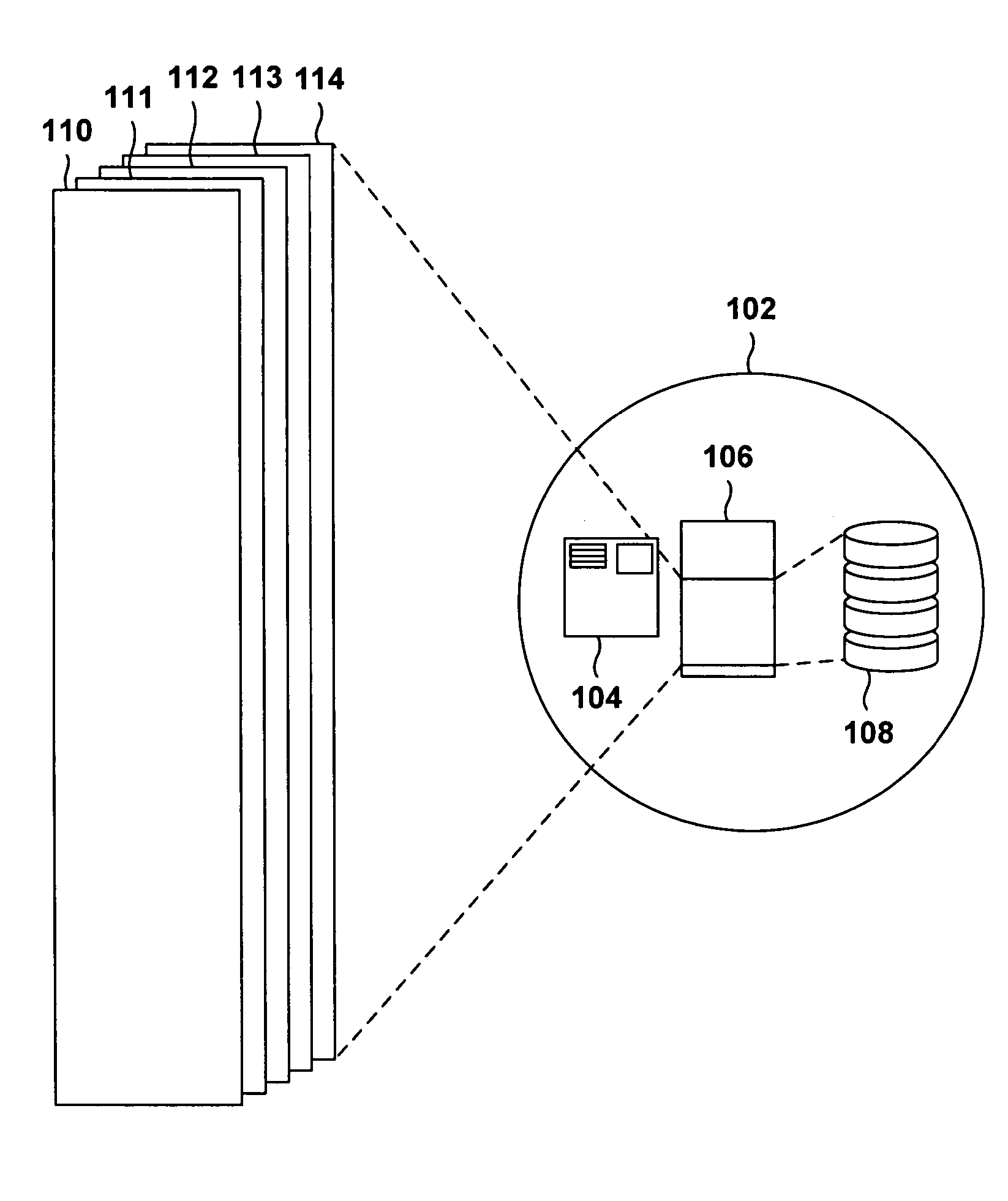
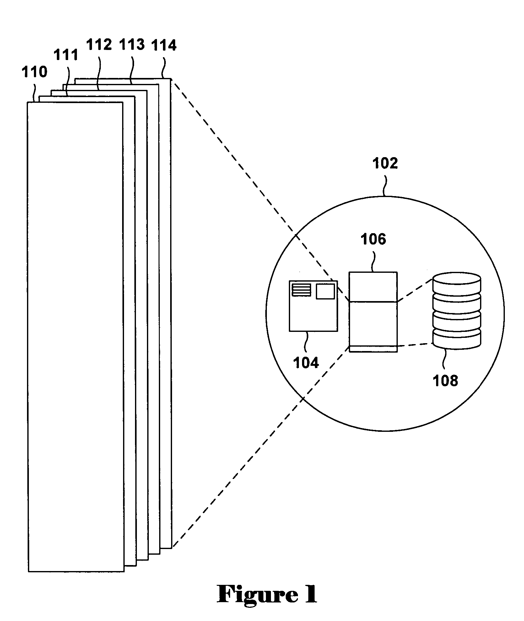
[0024]FIG. 1 illustrates virtual memory provided by a combined operating-system / hardware system. In FIG. 1, the operating system is abstractly represented as a circle 102 enclosing hardware components inc...


PUM


Abstract

Various embodiments of the present invention are directed to efficient provision, by a virtual-machine monitor, of a virtual, physical memory interface to guest operating systems and other programs and routines interfacing to a computer system through a virtual-machine interface. In one embodiment of the present invention, a virtual-machine monitor maintains control over a translation lookaside buffer (“TLB”), machine registers which control virtual memory translations, and a processor page table, providing each concurrently executing guest operating system with a guest-processor-page table and guest-physical memory-to-physical memory translations. In one embodiment, a virtual-machine monitor can rely on hardware virtual-address-translation mechanisms for the bulk of virtual-address translations needed during guest-operating-system execution, thus providing a guest-physical memory interface without introducing excessive overhead and inefficiency.

Description

CROSS REFERENCE TO RELATED APPLICATION[0001]This application is a continuation in part of U.S. patent application Ser. No. 10 / 909,965, filed Jul. 31, 2004 now abandoned.TECHNICAL FIELD[0002]The present invention is related to computer architecture, operating systems, and virtual-machine monitors, and, in particular, to methods, and virtual-machine monitors employing the methods, for efficiently virtualizing physical memory and virtual-address translation mechanisms.BACKGROUND OF THE INVENTION[0003]During the past 50 years, computer hardware, architecture, and operating systems that run on computers have evolved to provide ever-increasing storage space, execution speeds, and features that facilitate computer intercommunication, security, application-program development, and ever-expanding range of compatibilities and interfaces to other electronic devices, information-display devices, and information-storage devices. In the 1970's, enormous strides were made in increasing the capabil...

Claims


Application Information

Patent Timeline
Patent Type & Authority Patents(United States)
IPC IPC(8): G06F12/00G06F9/00
CPCG06F12/1036G06F12/109G06F12/1018
Inventor DE DINECHIN, CHRISTOPHEKJOS, TODDROSS, JONATHAN
Owner VALTRUS INNOVATIONS LTD
Learn More