Communications spooler for a mobile robot

a robot and communication technology, applied in the field of robotic systems and unmanned vehicles, can solve the problems of signal sent over wireless systems can suffer from limited range and radio or environmental interference, and human beings in similar situations are at risk, etc., to achieve the effect of zero tension and zero tension

Active Publication Date: 2008-02-19
FLIR DETECTION
View PDF13 Cites 135 Cited by
  • Summary
  • Abstract
  • Description
  • Claims
  • Application Information

AI Technical Summary

Benefits of technology

[0010]In another aspect, the invention relates to a mobile platform including: a chassis; a chassis drive system; a drive system sensor for determining platform velocity; a cable handling system secured to the chassis for dispensing and retrieving cable from the mobile platform at substantially zero tension; and a system controller for controlling the cable handling system, the controller determining an effective cable velocity based at least in part on platform velocity and platform configuration. In one embodiment of the foregoing aspect, the system controller utilizes a rigid body transform function. In various other embodiments of the foregoing aspect, the system controller manages a plurality of cable management modes, which may include: a track mode; a track reverse mode; a track in mode; a track out mode; an error mode; and/or an idle mode.
[0011]In another embodiment of the foregoing aspect, the mobile platform also includes: a cable reel mounted to the cable handling system; and a cable including a first end portion, an intermediate portion, and a second end portion, wherein the first end portion is secured to the cable reel, the intermediate portion is wound about the cable reel and guided through the cable handling system, and the second end portion is downstream of the mobile platform. In other embodiments of the foregoing aspect, the second end portion of the cable is secured to a remote base and may be at least one of a fiber optic cable and a power c

Problems solved by technology

Robots and robotic devices are used today to perform tasks traditionally considered dangerous or otherwise inappropriate for humans, due to size or environmental considerations.
For example, robots are often purposefully exposed to situations where the risk to a human being in a similar situation is too high.
Fiber optic cables are generally preferred over wireless transceivers, because signals sent over wireless systems can suffer from limited range and radio or environmental interference.
Also, in certain situations (e.g., near an explosive device), radio frequency transmissions may not be allowed.
These circumstances and restrictions can reduce the quality of communications and limit or end the mission.
This is often the case indoors or underground, due to interference with surrounding building structure.
Use of a tethered cable, however, does have its limitations, one of the most apparent being that cables trailed behind mobile robots can become snagged as the robot moves around corners or other obstacles.
These snags, in addition to effecting the motion of the robot by creating a dragging force a

Method used


Image

  • Communications spooler for a mobile robot
  • Communications spooler for a mobile robot
  • Communications spooler for a mobile robot

Examples


Embodiment Construction

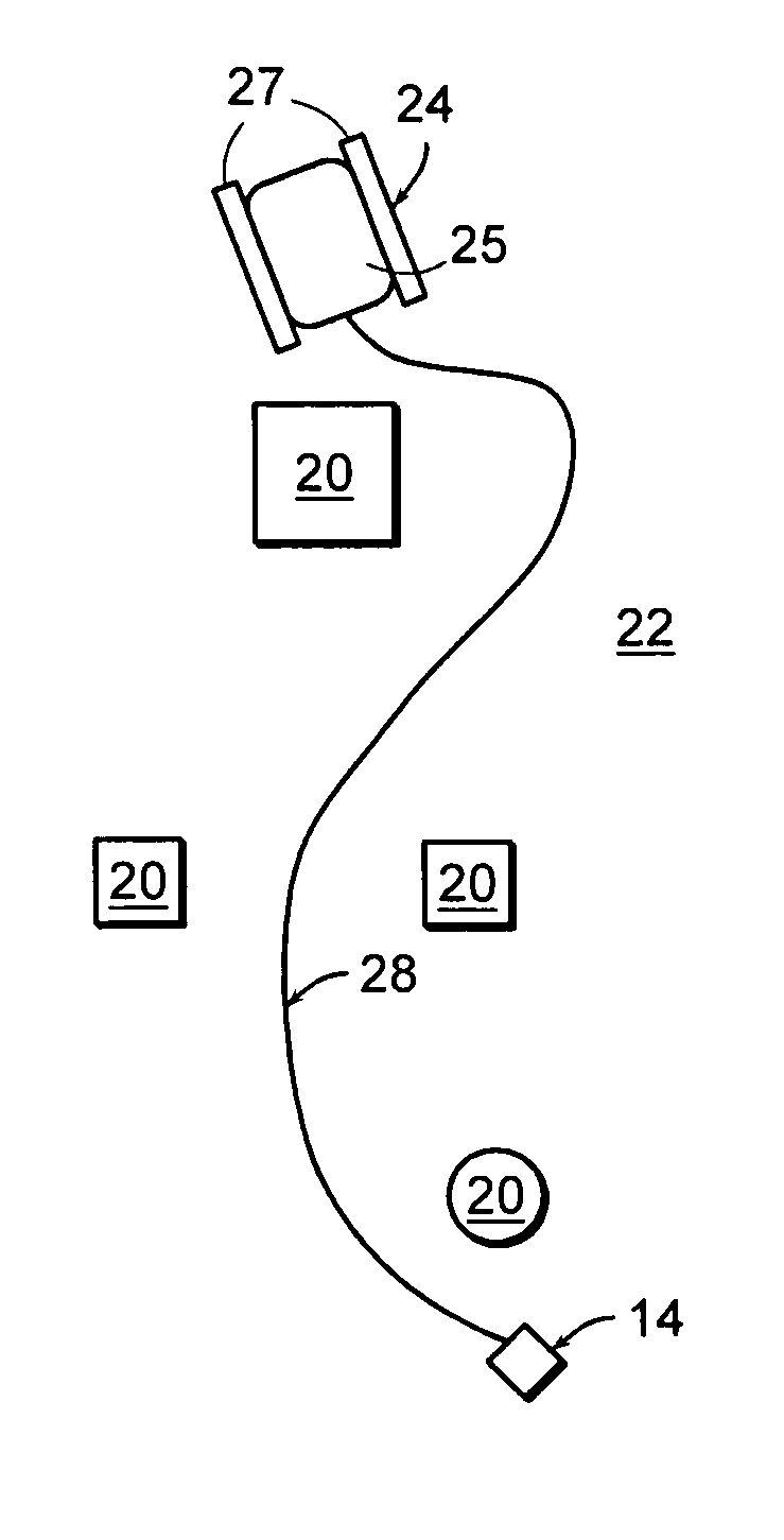
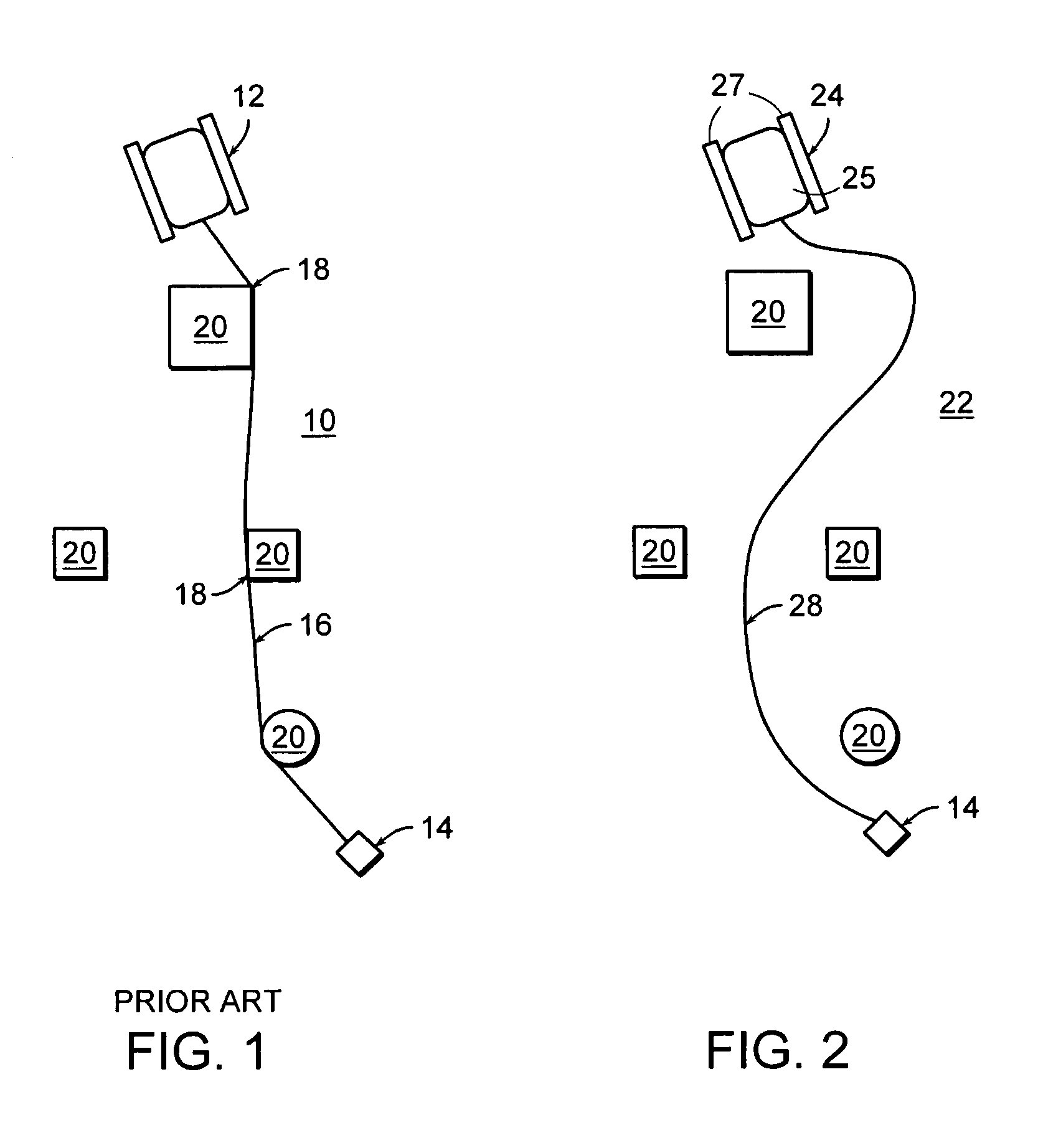
[0030]FIG. 1 is a schematic view of a mobile robot 12 employing a prior art cable handling system during operation. The robot 12 operates in an area 10, that may be either bounded (as within a room or other enclosed space) or unbounded (as being used outdoors). An operator (not shown) directs the robot 12 from or near a remote, stationary base 14. Generally, the operator navigates the robot 12 as required during the course of an appointed task, driving or otherwise guiding the robot 12 around and in between a number of obstacles 20. A cable 16 is dispensed from the robot 12 as it moves away from the base 14. Since the cable 16 is kept taut, it can get caught on the obstacles 20, creating kinks 18 as the cable bends around them. These kinks 18 can damage the cable 16 and effect the integrity of transmission of a signal along the cable 16. Additionally, the cable 16 is subject to high-tension loads that can have a detrimental effect on the longevity of the cable 16. The tension on the...


PUM


Abstract

A cable handling system mounted to a mobile robot to dispense and retrieve cable at zero tension includes a cable reel drive and a downstream tension roller drive that includes an idler. As a cable passes through the tension roller drive, position along the length of the cable and/or the cable speed is monitored accurately by a sensor attached to the idler. A system controller in communication with the sensor controls the cable reel drive and the tension roller drive for dispensing and retrieving cable downstream of the tension roller drive.

Description


Claims


Application Information

Patent Timeline
IPC IPC(8): H02G11/02
CPCB65H75/425B65H75/4484B65H75/4486F41H7/005F41H11/16F42B15/04H02G11/02
Inventor PACK, ROBERT TODDSAWYER, TYSONWON, CHIKYUNGMORE, GRINNELL
Owner FLIR DETECTION
Why Eureka
Try Eureka