Drive head assembly for a fluid conveyor system

a technology of fluid conveyor and drive shaft, which is applied in the direction of fluid removal, positive displacement liquid engine, borehole/well accessories, etc., can solve the problems of reducing the useful life of conveyor, slipping conveyor on the drive shaft, and reducing efficiency, so as to maximize the contact between the sheaves and the conveyor, improve the traction effect, and maximize the contact of the conveyor

Inactive Publication Date: 2010-09-23
CRAFTON JIM
View PDF4 Cites 2 Cited by
  • Summary
  • Abstract
  • Description
  • Claims
  • Application Information

AI Technical Summary

Benefits of technology

[0009]The preferred embodiment of the present invention provides an efficient and dependable device for driving a conveyor through the length of a well bore to collect fluids. The present invention incorporates two synchronized sheaves. A “figure-8” conveyor path between the synchronized sheaves maximizes the contact of the conveyor with the sheaves and not only improves traction between the sheaves and the conveyor but also allows for zero tension on the conveyor as it reenters the tubing in the well bore. The sheaves include coaxial grooves, each having a unique and novel cross-section that further improves traction without unnecessary abrasion on the conveyor. Under normal working load conditions, as measured by conveyor tension, the invention significantly increases conveyor lifespan.
[0010]Accordingly, an embodiment of the present invention provides a drive head assembly for a fluid conveyor which includes a double sided drive mechanism, such as gears or a double sided drive belt, engaged with a drive wheel and three follower wheels. A first follower wheel shares a rotational axis with a first sheave. A second follower wheel shares a rotational axis with a second sheave. The drive mechanism engages the first and second follower wheels in such a way as to impart a synchronous but opposite rotation to them. The first and second sheaves are connected to the first and second follower wheels respectively via shared rotational axes. The first and second follower wheels impart a synchronous but opposite rotation to the first and second sheaves. The first and second sheave each has a set of coaxial grooves. The preferred embodiment has four coaxial grooves on each sheave. Each groove on the first sheave matched to a groove on the second sheave to form a set of grooves. An endless conveyor follows a “figure-8” conveyor path, through each groove between the sheaves. The “figure-8” conveyor path maximizes the contact surface between the sheaves and the conveyor providing improved traction on the conveyor. The cross-sectional area of the conveyor expands as tension in the conveyor is reduced following each loop around the pair of sheaves. Similarly, the width of each consecutive groove increases to accommodate the conveyor. The depth of each groove, between the lowest portion of each groove and the center of the sheave, is also related to the cross-sectional area of the conveyor. The first groove of each sheave is slightly shallower than that of the adjacent groove which is slightly shallower than the next adjacent groove and so forth. As a result of the progressive increase in depth of each groove, the distance between the cross-sectional center of the conveyor and the rotational axis is slightly reduced in each consecutive groove of the sheave. The conveyor travels down a two-channeled tubing to a remote sheave and returns up the tubing to the sheaves entraining fluid from a reservoir. The drive head assembly of the present invention is surrounded by a sealed cover. The cover, which acts as a containment vessel, protects the environment from the fluids lifted. Additionally, the cover allows a pressurized interior, if necessary, and collects the fluid entrained on the returning conveyor. An outlet port in the cover directs the collected fluid to a holding tank.

Problems solved by technology

Efficiency is lost when the conveyor slips on the drive sheave due to low traction between the conveyor and the sheave.
Slippage causes wear on the conveyor and therefore reduces its useful life.
A common problem with the fluid conveyors of the prior art is the failure of the conveyor due to slippage or high tension.
The relatively short lifespan of the conveyor increases the cost of the system which is a distinct disadvantage of the prior art.
The tension in the belt and the skimming process needed to remove the liquid from both sides of the belt tend to shorten the lifespan of the belt.
The useful life of the rope is diminished by the contact with the ridges in the groove and the scraping of the wipers.
The squeezing of the belt exposes the belt to additional abrasion and hence limits its lifespan.
The constant tension in the rope, especially on the downward side of the loop puts undue strain on the rope and reduces its lifespan.

Method used


Image

  • Drive head assembly for a fluid conveyor system
  • Drive head assembly for a fluid conveyor system
  • Drive head assembly for a fluid conveyor system

Examples


Embodiment Construction

[0024]In the descriptions that follow, like parts are marked throughout the specification and drawings with the same numerals, respectively. The drawing figures are not necessarily drawn to scale and certain figures may be shown in exaggerated or generalized form in the interest of clarity and conciseness.

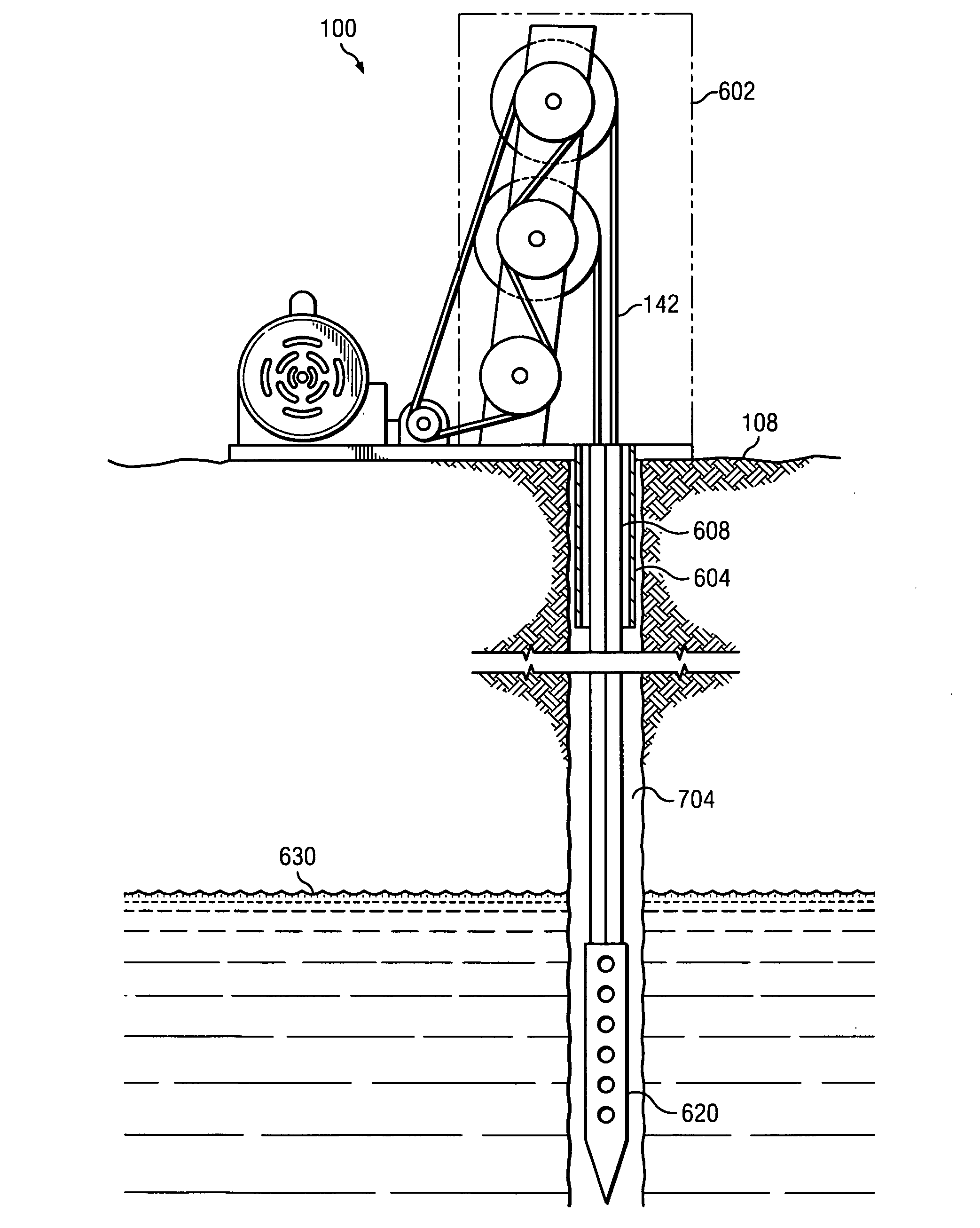
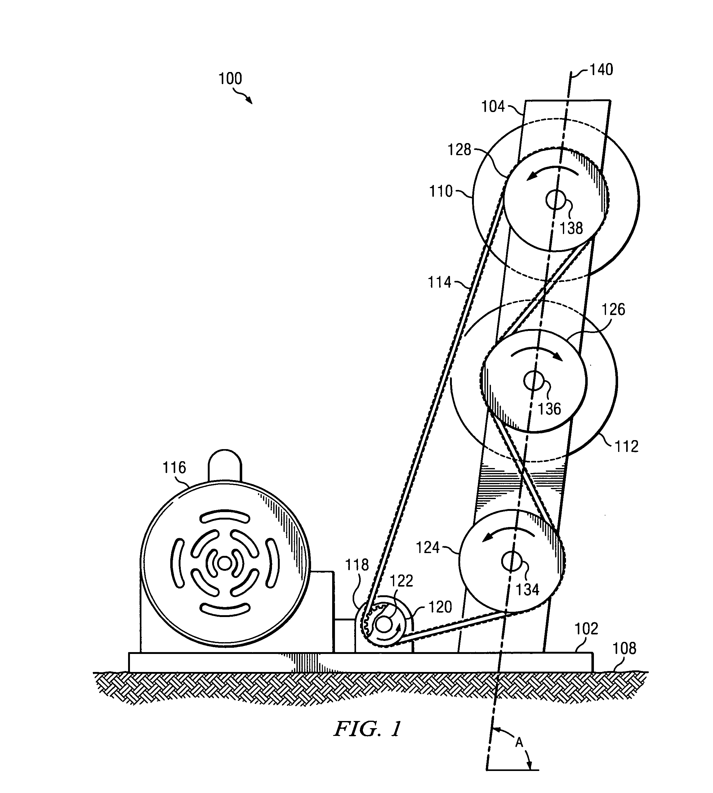
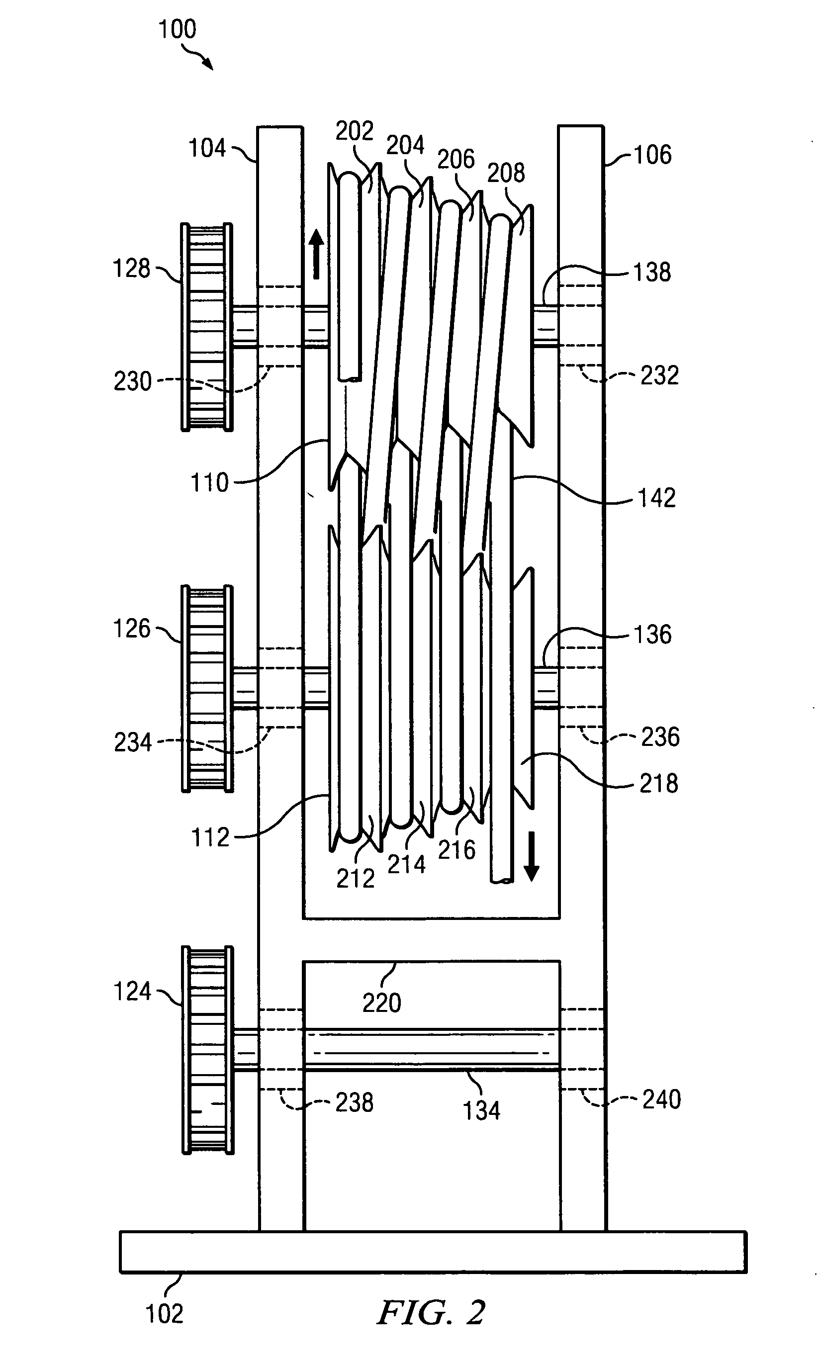
[0025]FIGS. 1, 2 and 6 show a preferred embodiment of drive head 100. Base 102 provides a connecting platform for motor 116, transmission 118, and frames 104 and 106. In the preferred embodiment, base 102 is mounted to ground surface 108 via a concrete slab. Brace 220 stabilizes frame 104 to frame 106. Frames 104 and 106 are parallel to each other and extend from base 102 at angle A. Angle A may be any angle, including perpendicular. In the preferred embodiment, angle A ranges from 80° to 85°.

[0026]In the preferred embodiment, motor 116 generates up to 10 horsepower and is powered by fuel or electricity. However, motor 116 may be of any size or type. The size of motor 116 may be al...


PUM


Abstract

The invention disclosed provides a drive head assembly for a fluid conveyor system that propels a fluid entraining conveyor through a well bore to carry fluids to the surface. The invention is comprised of a pair of synchronized follower wheels connected to a set of counter rotating sheaves. A fluid entraining conveyor is wrapped in a “figure-8” conveyor path around the sheaves in a plurality of coaxial grooves and around a distal sheave located in the fluid in the well bore. The coaxial grooves incorporate a unique shape which in conjunction with the wrap pattern provide improved tractive qualities and thus reduce tension in the conveyor and increase the durability of the conveyor. The conveyor can run at increased speeds and with no tension on the downward portion of the conveyor resulting in higher efficiency and less down time due to breakage.

Description

CROSS-REFERENCE TO RELATED APPLICATIONS[0001]This application claims priority to U.S. Provisional Application No. 61 / 192,432 entitled “Drivehead Assembly For A Rope Pump System,” filed on Sep. 18, 2008.FIELD OF THE INVENTION[0002]The present invention relates to an improved method and apparatus for moving fluid. In particular, the invention relates to a synchronized drive head assembly containing a set of counter rotating sheaves with an endless conveyor and used to move fluids.BACKGROUND OF THE INVENTION[0003]Using a continuous rope or belt as a conveyor looped between a sheave at a particular destination and a sheave at a particular origin to move fluid is known in the prior art. Often the fluid conveyor is used to lift water or oil from beneath the surface of the ground to a storage receptacle on the surface. In this specific use of lifting fluid up to the surface, a well bore of sufficient length to reach the fluid is drilled and a fluid entraining conveyor or belt is secured ar...

Claims


Application Information

Patent Timeline
Patent Type & Authority Applications(United States)
IPC IPC(8): E21B43/12F04B19/16B65G15/00
CPCF04B19/16E21B43/121
Inventor CRAFTON, JIM
Owner CRAFTON JIM
Why Eureka
Try Eureka