Retractable ice cooler

a retractable, cooler technology, applied in the field of ice-based portable coolers, can solve the problems of large size, inconvenient operation, and inability to adjust the temperature, and achieve the effects of convenient operation, convenient operation, and convenient storag

Inactive Publication Date: 2017-09-07
KRIESEL ROGER MARK
View PDF14 Cites 22 Cited by
  • Summary
  • Abstract
  • Description
  • Claims
  • Application Information

AI Technical Summary

Benefits of technology

[0025]This new embodiment of a portable ice cooler provides numerous improvements beyond the current state of the art: (A) A simple internal roller mechanism and mesh fabrics are employed to retract the ice from the cooled items. The capacity to retract the ice away from the cooled items prior to their retrieval or replenishment is a distinguishing feature. The perforated, lightweight, and conformable qualities of the mesh fabrics deliver two advantages: (1) they provide a strong, reliable, and compact means to separate the ice and cooled items; and (2) whenever retraction of the ice is not needed, they promote efficient cooling by permitting the ice and cooled items to retain close proximity to one another. (B) Restocking of the cooler can be performed either when it is positioned on its back or when it is upright. Restocking of the cooler with it on its back is the simplest and fastest method because items can simply be dropped inside. (C) A smooth long radius curvature forms the external contour of the cooler where the rear exter...

Problems solved by technology

The advantages these features provide are an unparalleled degree of comfort, speed, and ease of access to the desired items in the cooler.
Furthermore, these advantages are achieved with only a negligible reduction in the storage capacity and cooling efficiency.
There are two main problems with the current state of the art: Compartmentalized coolers are rare and their larger size and reduced cooling efficiency are likely drawbacks that are disfavored by consumers.
Alternatively, coolers that are accessed through a top door fre...

Method used


Image

  • Retractable ice cooler
  • Retractable ice cooler
  • Retractable ice cooler

Examples


first embodiment

—First Embodiment

FIG. 1, 2, 3

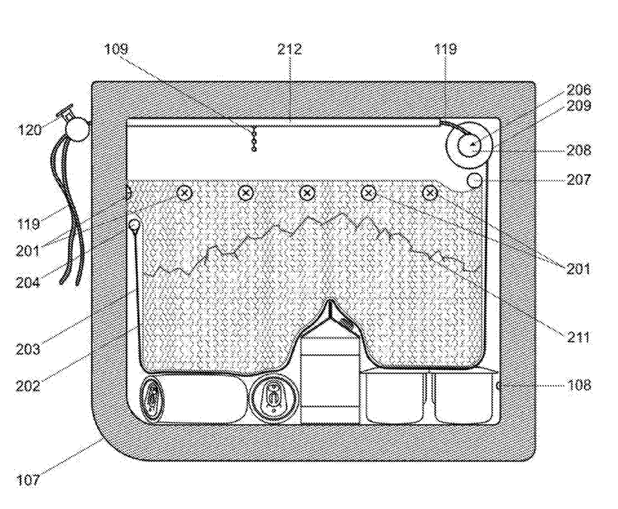
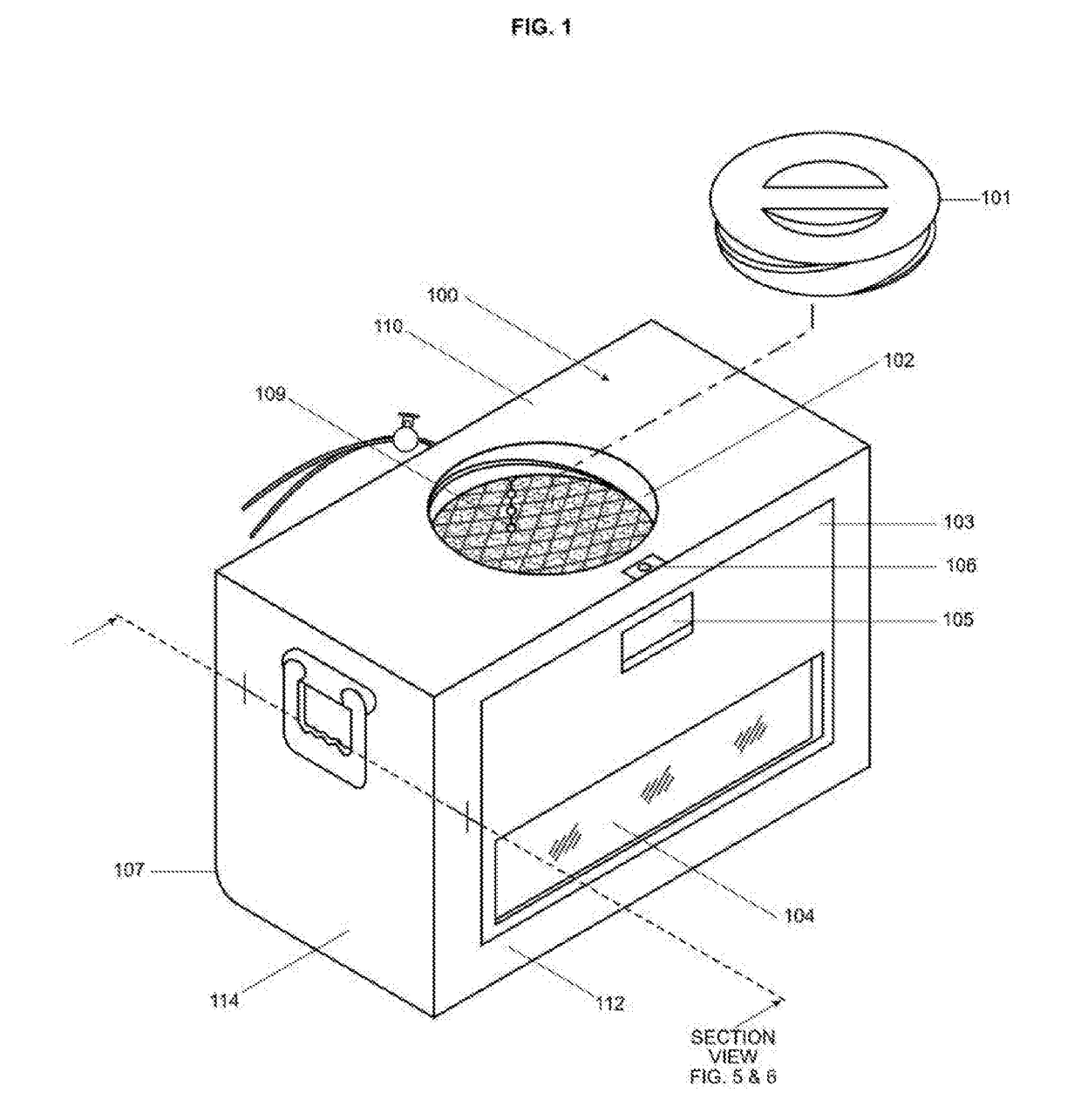
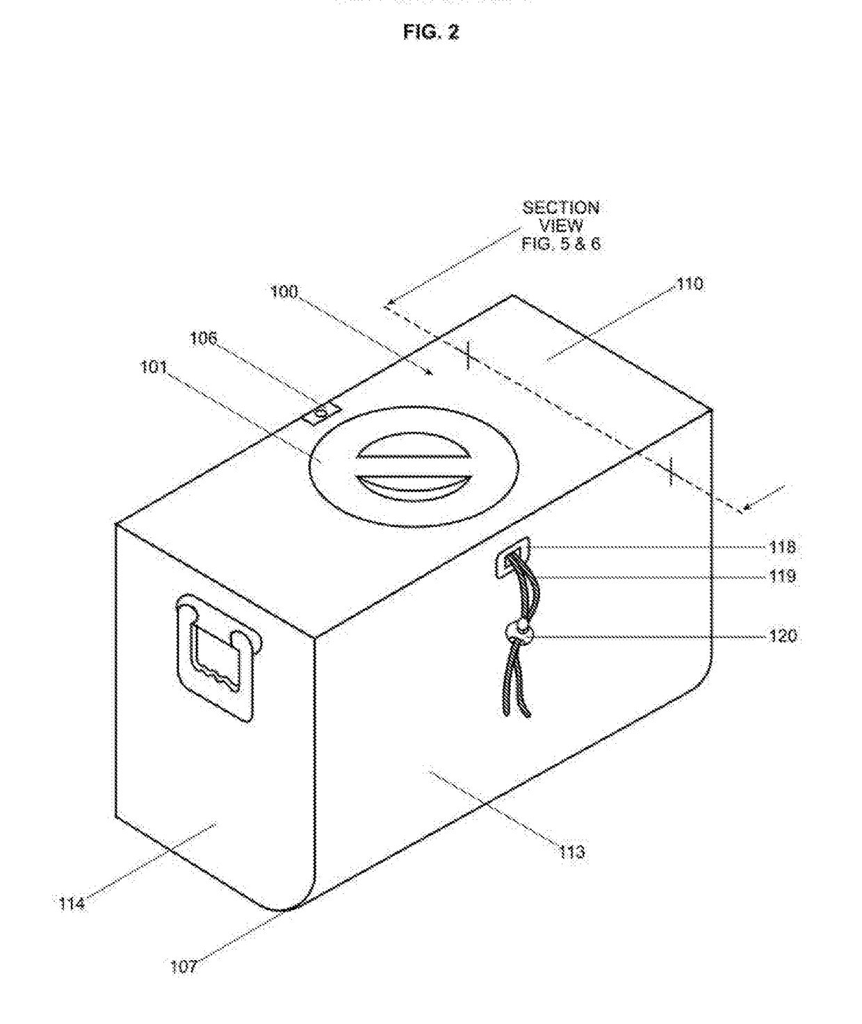
[0036]The process of making the Retractable Ice Cooler 100 involves molding a thermally insulated plastic cooler typically in a cube or rectangular shape. The Cooler 100 is constructed such that it has a Removable Fill Cap 101, a Fill Opening 102 and a single Bottom-Pivoting Front Door 103. The Top 110 of the Cooler 100 is typically a flat surface continuously molded with the adjacent vertical sides of the cooler. The Removable Fill Cap 101 is a circular threaded and thermally insulated removable cap of a predetermined diameter suitable for the placement of Ice 211 into the Cooler 100. Inside the Cooler 100 immediately adjacent to the Fill Opening 102 is a Fill Level Indicator 109. The Fill Level Indicator 109 suspends from the inside Top 110 of the Cooler 100. The Indicator 109 is a high visibility, flexible, weighted, beaded line similar to a pull chain for a light. The suspended end of the Indicator 109 serves as a visual cue of the maximum depth to w...


PUM


Abstract

One embodiment of an improved portable ice cooler that eases access to the cooled contents by integrating in a single apparatus an adjustable ice containment device, a front door, a window, internal lighting and a specialized external contour. The benefits these features provide are a significant reduction in the discomfort and difficulty currently encountered when placing, locating, and removing contents from a current state of the art ice cooler that is accessed from the top or front. The ice containment device further offers the capability of holding a desired level of retraction to the ice within the cooler. The provision for retraction of the ice and thereby the ability to adjust both the proximity of the ice to the items in the cooler as well as the weight of the ice upon those items can be utilized to cool fragile objects.

Description

COPYRIGHT NOTICE[0001]A portion of the disclosure of this patent document contains material which is subject to copyright protection. The copyright owner has no objection to the facsimile reproduction by anyone of the patent document or the patent disclosure, as it appears in the Patent and Trademark Office patent file or records, but otherwise reserves all copyrights whatsoever.CROSS-REFERENCE TO RELATED APPLICATIONS[0002]Not ApplicableFEDERALLY SPONSORED RESEARCH[0003]Not applicableBACKGROUND OF THE INVENTION[0004]This apparatus is associated with the field of endeavor of ice-based portable coolers designed for the purpose of storage of perishable or otherwise heat-sensitive items. Its purpose is to improve the functionality of the cooler by: (1) faster and more comfortable access to the contents, (2) faster restocking, (3) reduced ice spillage, and (4) the provision of an adjustable mechanism to manipulate the proximity of the ice to the contents.BACKGROUND OF THE INVENTION—PRIOR...

Claims


Application Information

Patent Timeline
IPC IPC(8): F25D3/08F25D27/00F25D3/06
CPCF25D3/08F25D3/06F25D2303/0844F25D2303/081F25D27/00
Inventor KRIESEL, ROGER MARK
Owner KRIESEL ROGER MARK
Why Eureka
Try Eureka