Microfluidic Biological Extraction Chip

Active Publication Date: 2010-05-06
CFD RES COPORATION
View PDF20 Cites 26 Cited by
  • Summary
  • Abstract
  • Description
  • Claims
  • Application Information

AI Technical Summary

Benefits of technology

[0010]In one aspect, the present invention is a microfluidic extraction cartridge and method comprising a bead-based capture and elution chamber comprising a loosely packed, fluidized solid supports, such as beads. By “loosely packed, fluidized”, it is meant that the solid supports are not static, as in a packed column, but rather free to move r

Problems solved by technology

Patterned electrode structures, while being the most direct way of attaining the large electric fields needed for cell lysis, int

Method used


Image

  • Microfluidic Biological Extraction Chip
  • Microfluidic Biological Extraction Chip
  • Microfluidic Biological Extraction Chip

Examples


Example

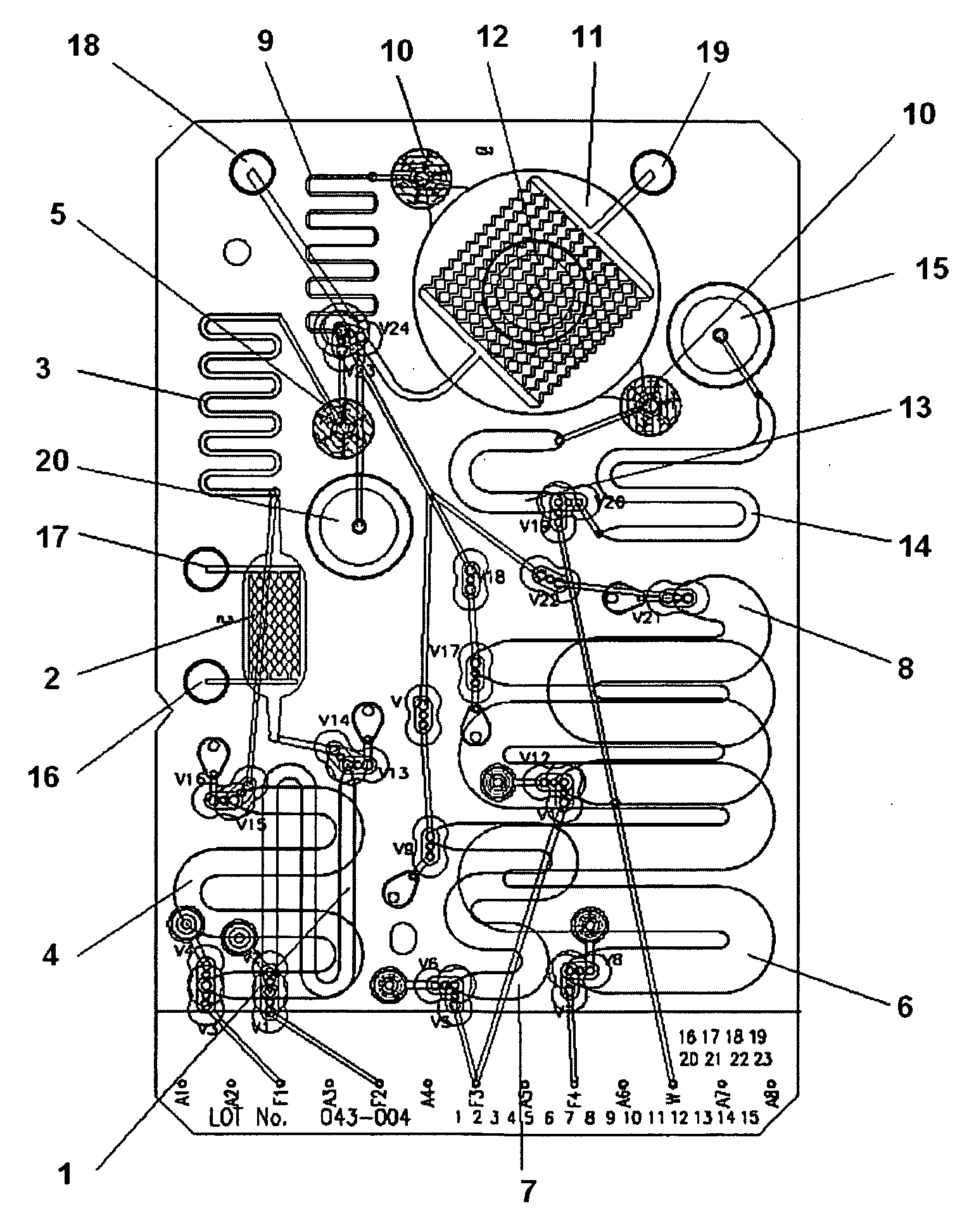
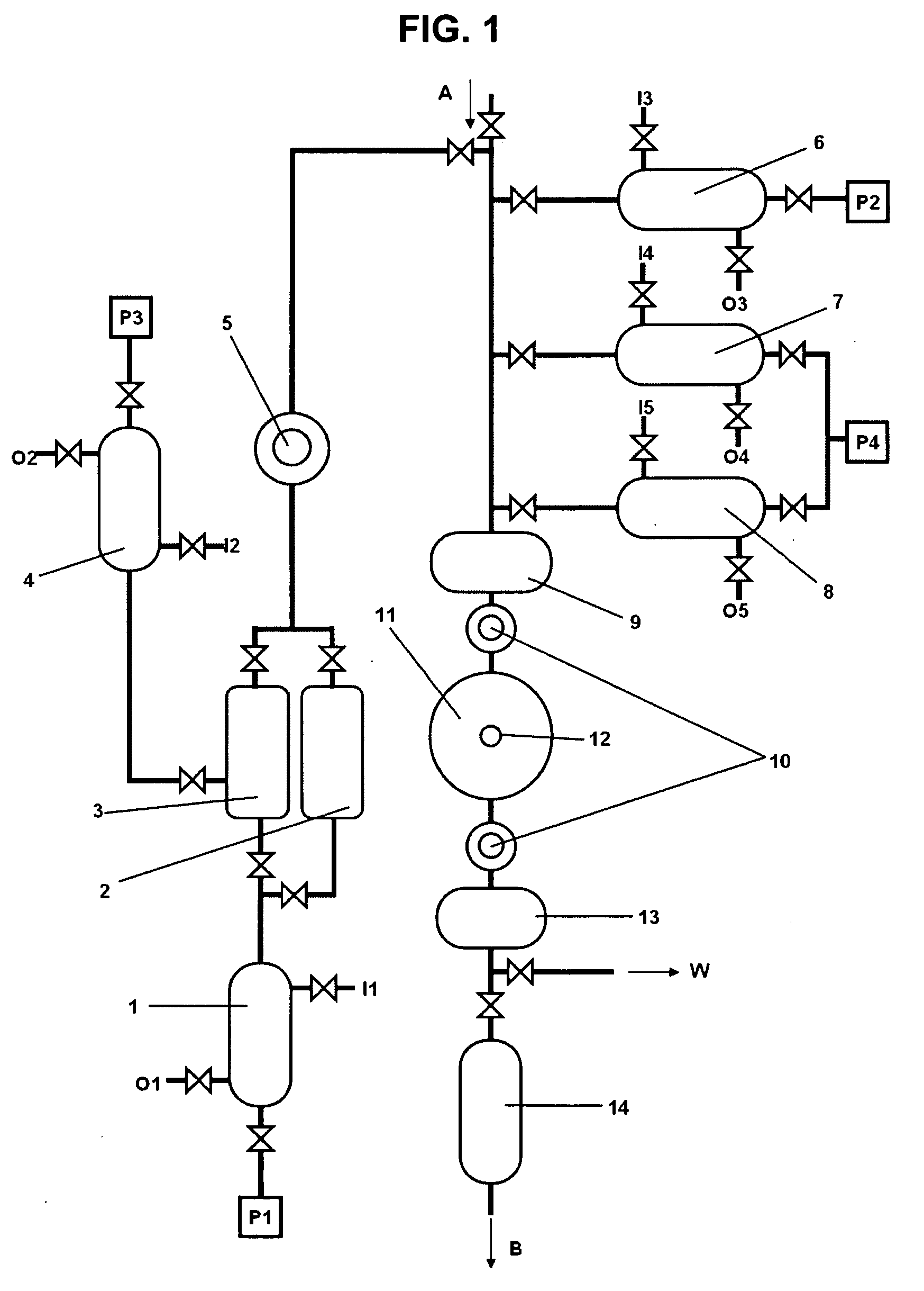
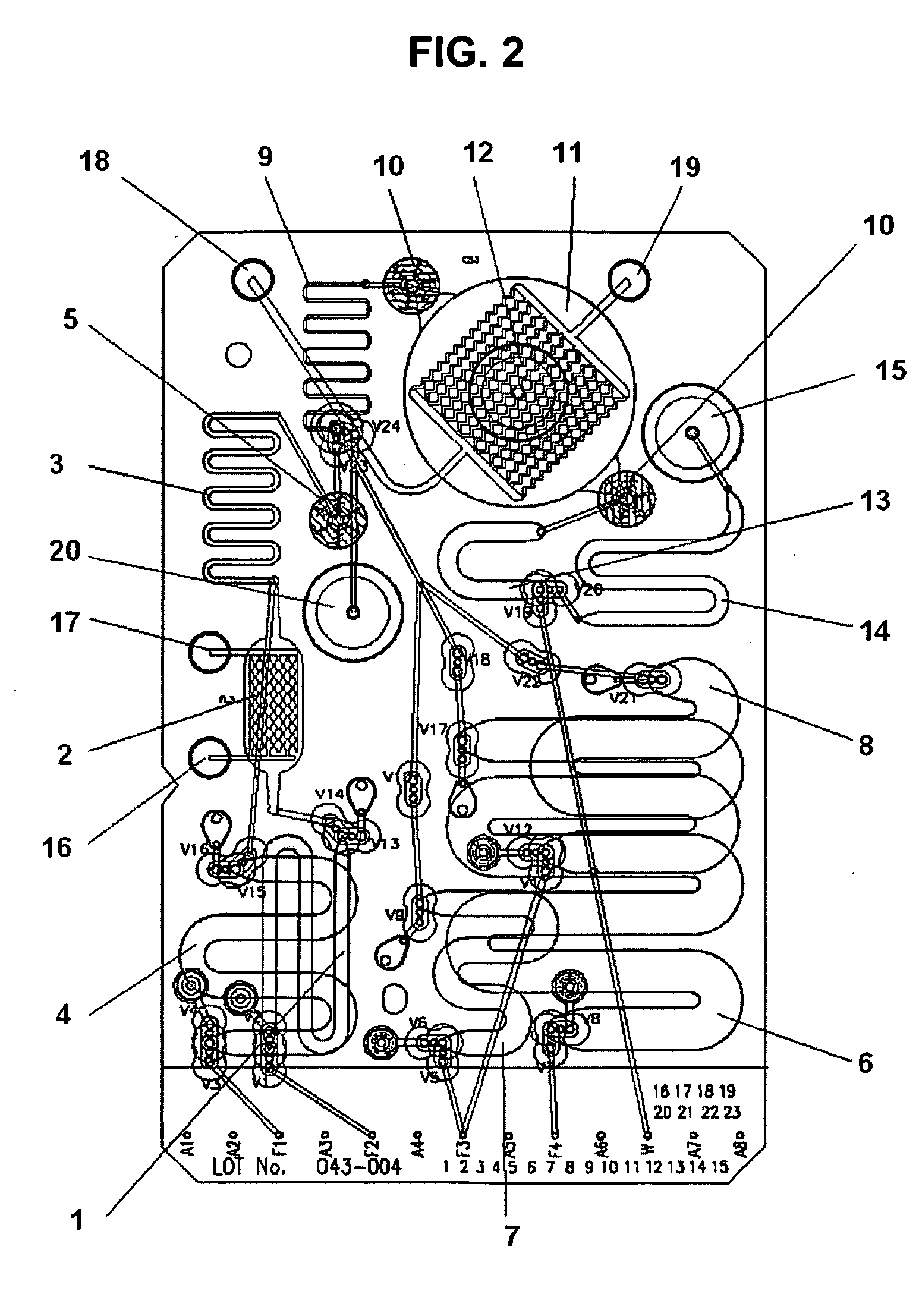
[0023]FIG. 1 illustrates the layout of a first embodiment of a microfluidic extraction cartridge. The cartridge is configured for the extraction of nucleic acids from cells or cell lysate but other embodiments may be configured for the extraction of protein, protein fractions, or other cellular contents by altering the binding properties of the beads used for molecular capture. Additionally, the lysis chambers may be configured and operated to disrupt other sources of DNA or RNA such as viruses or bacterial or fungal spores. Table 1 lists the structural elements identified in FIG. 1.

TABLE 11Sample Loop2Electric Field Lysis Chamber3Chemical Lysis Chamber4Chemical Lysis Reagent Loop5Lysate Filter Membrane6Wash Buffer Loop7Nuclease Solution Loop8Elution Buffer Loop9Contacting Loops10Bead Containment Membranes11Capture Chamber12Bead Injection Port13Buffer Chamber14Product Storage ChamberP1Pump 1P2Pump 2P3Pump 3P4Pump 4

[0024]Sample Loop 1 may be loaded with cells, spores, virions or othe...


PUM

PropertyMeasurementUnit
Pressureaaaaaaaaaa
Shapeaaaaaaaaaa
Electric propertiesaaaaaaaaaa

Abstract

A microfluidic cartridge for isolating biological molecules having a capture chamber containing functionalized solid supports maintained in a fluidized state provides reduced pressure drops and bubble formation during microfluidic extraction. The cartridge may include an electric field lysis chamber and/or a chemical lysis chamber. The electric-field lysis chamber may comprise an electrically insulating structure arranged between two opposing planar electrodes.

Description

STATEMENT REGARDING FEDERALLY SPONSORED RESEARCH OR DEVELOPMENT[0001]The U.S. Government has rights in this invention under Contract No. NNJ05JA04C.CROSS-REFERENCE TO RELATED APPLICATIONS[0002]Not ApplicableINCORPORATED-BY-REFERENCE OF MATERIAL SUBMITTED ON A COMPACT DISC[0003]Not ApplicableBACKGROUND OF THE INVENTION[0004]1. Field of the Invention[0005]The present invention is a microfluidics-based cartridge for automated extraction of biological molecules from cells, spores, virions, their lysates, and other biological samples. The present invention is capable of isolating nucleic acids, proteins, and other biological macromolecules from less than 10,000 cells in 30 minutes.[0006]2. Description of Related Art[0007]Microfluidic apparatus and methods for the lysis of cells and / or separation of selected lysate components are known in the art. U.S. Pat. No. 6,287,831 B1 to Tai et al. discloses a cell lysis device in which micromachined electrodes spaced less than 100 micrometers apart...

Claims


Application Information

Patent Timeline
IPC IPC(8): C12N7/00C12M1/00C12N5/06C12N1/06
CPCC12M47/06C12N15/1006Y10T436/11
Inventor SUNDARAM, SHIVSHANKARPRABHAKARPANDIAN, BALABHASKARPANT, KAPILWANG, YI
Owner CFD RES COPORATION
Why Eureka
Try Eureka