Bone block assemblies and their use in assembled bone-tendon-bone grafts

a technology of bone tendons and bone tendons, which is applied in the field of bone tendons, can solve the problems of low availability of human allograft materials, high recovery costs, significant constraints on the ready use of such materials, and achieve enhanced gripping characteristics, enhanced tensile strength, and enhanced gripping of soft tissue

Active Publication Date: 2010-07-27
RTI BIOLOGICS INC
View PDF133 Cites 26 Cited by
  • Summary
  • Abstract
  • Description
  • Claims
  • Application Information

AI Technical Summary

Benefits of technology

[0015]These compression surfaces and cavities (i.e., enhanced gripping features) result in a BTB graft that has the advantages of full internal tendon capture and bone to bone contact at the healing interface, and allow the use of any suitable soft tissue (e.g., tendon) specimen, construction to a predetermined gage length, and adherence to preferred surgical technique and fixation methods, while maintaining a significantly increased tensile strength over BTBs formed by stitching, stapling or compression alone.
[0016]It was also unexpectedly discovered that when the cross-sectional shape of the cavity (preferably, a channel) was omega shaped, an even more enhanced gripping of the soft tissue (e.g., tendon) between the opposing faces of the bone blocks was achieved. It is believed that the undercut shape of the omega cavity allows it to advantageously capture and hold the uncompressed and overflow soft tissue. Specifically, the omega cavity has a unique shape because it has a narrower mouth than the width of its cross section due to the fact that the face of the bone block is undercut and the undercut is rounded. This feature allows the soft tissue to enter the cavity and expand in a direction opposite to the direction of the compressed soft tissue immediately above on the tissue engaging surface of the bone block. The rounded profile also greatly reduces stress concentrations and allows the soft tissue to distribute the compressive load more evenly across the entire cavity. As a result, the omega cavity gently grips the soft tissue without cutting, and prevents it from slipping, sliding or flowing in the direction it is being pulled or squeezed. Moreover, unlike the edges of teeth or ridges (see FIGS. 6A-6D) that concentrate force on a tissue at all times during compression, the edge of the omega cavity only exerts force when needed in response to the tissue therein being pulled or squeezed. In addition, the narrow mouth of the omega cavity (or channel) on the bone block surface provides an additional benefit by maximizing contact (and thus grip) between the soft tissue (e.g., tendon) and the tissue engaging surface of the bone block.
[0020]The layout of the cavities and / or channels is also within the scope of this invention. In its simplest form, the cavity can be a single hole in the surface of the bone block with an omega shaped sidewall. Alternatively, the cavity can be a pocket or larger hole made by removing an area of material with an undercut around some or all of the periphery. When the cavity is a single channel or a plurality of channels, the channel(s) can run in the direction of pull of the tendon (FIGS. 12A-12D), or across the direction of pull of the tendon (FIGS. 13A-13D), or at an angle to the direction of pull of the tendon (FIGS. 16A-16D). In one embodiment of the present invention, the intermediate bone block has two channels with an omega cross-section running in the direction of pull of the tendon. See FIGS. 11A-11D. It is also within the scope of the present invention that one or both ends of the bone block have the edge of the tendon engaging face reduced. Typically, this is performed by sanding, routing, grinding or cutting the edge to produce a round, beveled or chamfered edge. See FIGS. 12A-12D. Preferably, this reduction of the end of the tendon engaging face results in an internal leading edge configuration that reduces tissue stresses during assembly and use. It is also within the scope of the present invention that the cross-sectional size of the cavities in any layout be the same (FIGS. 13A-13D) or different (FIGS. 14A-14D). It is additionally within the scope of this invention for the intermediate bone block to have an overall lengthwise tapering profile. See FIGS. 36A-36D.

Problems solved by technology

However, use of autograft materials is attended by the significant disadvantage that a second site of morbidity must be created to harvest autograft for implantation into a first diseased or injured site.
However, use of such materials has the disadvantage that human allograft materials are frequently low in availability and are high in cost of recovery, treatment and preparation for implantation.
By contrast, while xenograft implant materials, such as bovine bone, may be of ready availability, immunological, regulatory and disease transmission considerations imply significant constraints on the ready use of such materials.
However, this technique is often not possible, especially when the damage to the ligament is extensive.
These conventional techniques are not without their shortcomings; in most cases, the repaired joint lacks flexibility and stability.
Despite these realized advantages, there have been some difficulties encountered with utilizing bone / tendon grafts.
For example, surgical procedures involving transplantation and fixation of these grafts can be tedious and lengthy.
Further, surgeons must establish a means of attaching the graft, which also takes up valuable surgery time.
Tendons (or ligaments) are fibrous semi-hard materials that are slippery and difficult to grip.
Thus, one of the issues in manufacturing an assembled BTB is how to attach the slippery tendon to the bone.
However, teeth or threads have a tendency to cut into the tendon fibers when the tendon is pulled at high tensile strength.
Thus, most assembled BTBs provide some sort of trade-off between reducing slipping and squirming by biting which does not allow for achievement of maximum tensile strength.
One problem with such a device is that the screw, although bio-compatible, will never become assimilated into the patient's body.
A second problem is that the tendon or ligament will never form a natural attachment to the screw.
It is more difficult to pull a predetermined tension on the tendon because the tendon slips in the bone tunnel and uncontrollably alters the tension when the interference screw is being threaded in the bone tunnel.
The slippery ligament is also subject to slippage when compressed between the bone block and the tunnel wall.
Such slippage results in a loss of tension in the joint.
In the case of an anterior cruciate ligament (ACL) repair, this loss of tension causes a wobbly knee.
This is undesirable in any human and particularly athletes.
This leads to impaired healing and recovery due to tendon to bone contact within the tunnel and also due to micromotions of the tendon within the tunnel.
Additionally, the location of the tendon in the locking grooves is a function of the anchor body design and is not a controlled design parameter.
Thus, the tendon placement with respect to either the tunnel wall or the tunnel centerline cannot be matched to particular surgical needs or to surgeon preference.
While all of these embodiments are useful, they each are challenging to manufacture and / or assemble due to their inherent complexity and reliance on small or intricate parts.
One problem is that only 2-3 grafts can be obtained per knee of the donor, depending upon the donor's age and health.
Another problem with pre-shaped (natural) BTBs is that the size of the BTB or the length of the tendon between the two bone pieces cannot be precisely selected.
Frequently, this leads to compromises such as excessive gage length, or length between the bone blocks, which result in surgical challenges and compromised healing and recovery.
For example, a natural BTB with a tendon that is too long for an ACL repair results in having a length of unsecured and wobbling tendon in the bone tunnel between the ends of the secured bone portions.
The wobbling tendon hinders healing in the bone tunnel.

Method used


Image

  • Bone block assemblies and their use in assembled bone-tendon-bone grafts
  • Bone block assemblies and their use in assembled bone-tendon-bone grafts
  • Bone block assemblies and their use in assembled bone-tendon-bone grafts

Examples


example 1

Intermediate Bone Blocks of the Invention Having an Omega-Shaped Cross-Section

A. Plank with Two Substantially Parallel Channels Having an Omega-Shaped Cross-Section:

[0134]Cortical bone from a long bone shaft was cut into planks using a band saw. Bone planks were then cut into rectangular bone blanks of rough dimensions 10 mm×5 mm×25 mm using a mill (Haas Automation, Oxnard, Calif.; model # TM-1, serial # 34798). Each blank is then squared up and surface cut (planed) to final dimensions. One of the squared up bone blanks was laid out and templated for cutting two channels running the length of the bone blank and substantially parallel to the sidewalls of the bone blank. The rough outlines of the omega-shaped channels were cut with a 1.0 mm diameter end mill cutter. A 2.4 mm diameter ball end mill (Dremel, Racine Wis.; Dremel # 107) was used to complete the omega-shaped channels as shown in FIG. 11, for the final dimensions of 1.8 mm deep.

B. Plank with a Single “U”-Shaped Layout of Ch...

example 2

Bone Block Assembly Comprising an Intermediate Bone Block and a Second Bone Block

A. Bone Block of FIGS. 6A-6D with Saw Tooth Pattern of Ridges

[0139]Cortical bone planks were cut from a long bone shaft using a band saw. Bone planks were then cut into rectangular bone blanks of rough dimensions 10 mm×5 mm×25 mm using a mill (Haas Automation, Oxnard, Calif.; model # TM-1, serial # 34798). The mill was used to cut the serrated pattern of FIGS. 6A-6D on the upper block from a bone blank, at 0.76 mm deep, with a pitch of 0.8 teeth per mm, and at tooth angle of 30 degrees.

B. Intermediate Bone Block of FIGS. 11A-11D

[0140]The bone block of Example 2A was clamped to a surface with its ridge side up and the rough outline of two substantially parallel channels with an omega-shaped cross section were cut into the block with a 1.0 mm end mill cutter. A 2.4 mm diameter ball end mill (Dremel, Racine Wis.; Dremel # 107) was used to complete the two omega-shaped channels to produce the intermediate b...

example 3

A Bone Tendon Assembly for Testing Grip of Bone Patterns

A. Bone Block with a Smooth Tendon Engaging Surface

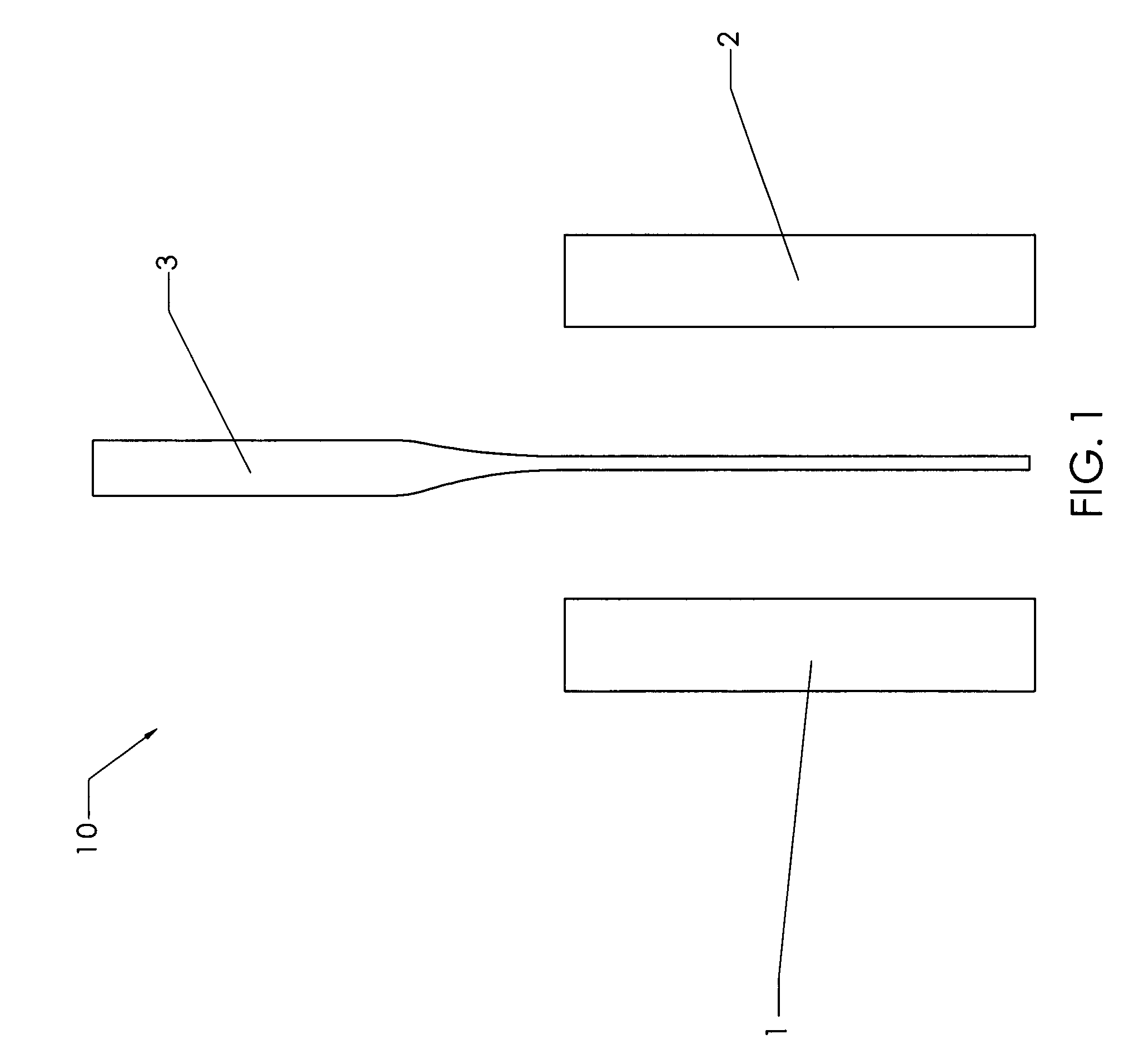
[0141]Cortical bone from a long bone shaft were cut into planks using a band saw. Bone planks were then cut into rectangular bone blanks of rough dimensions 10 mm×5 mm×25 mm using a mill (Haas Automation, Oxnard, Calif.; model # TM-1, serial # 34798). Each blank is then squared up and surface cut (planed) to final dimensions. A pair of these bone blocks were used to make the bone block-tendon assembly of FIG. 1.

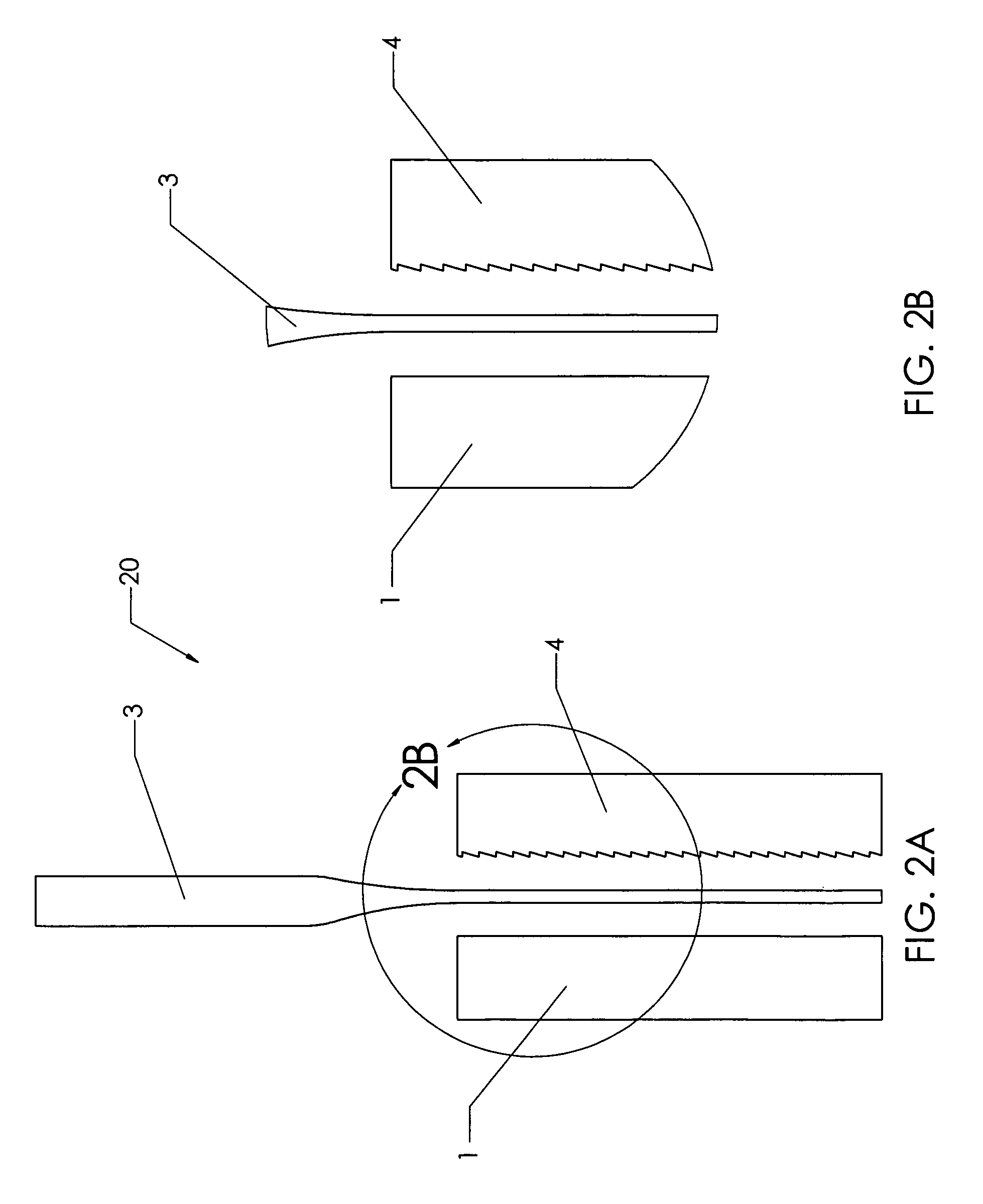
B. Bone Block with a Saw Tooth Pattern on the Tendon Engaging Surface of 0.8 Teeth per mm, 0.76 mm deep, at a 30 Degree Angle to the Direction of Pull of the Tendon

[0142]Cortical bone planks were cut from a long bone shaft using a band saw. Bone planks were then cut into rectangular bone blanks of rough dimensions 10 mm×5 mm×25 mm using a mill (Haas Automation, Oxnard, Calif.; model # TM-1, serial # 34798). The mill was used to cut the serrated pattern of FIGS. 6A-6D on ...


PUM


Abstract

The present invention has multiple aspects. In its simplest aspect, the present invention is directed to an intermediate bone block comprising a machined segment of cortical bone, cancellous bone or both, the intermediate having a face comprising one to ten compression surfaces and one to ten cavities, the compression surfaces suitable for compressing soft tissue, the cavities for receiving and holding overflow soft tissue. The cavities are preferably channels, and more preferably channels having an omega cross-sectional profile. The invention is also directed to bone block assemblies suitable for binding to a soft tissue to form an implantable graft, and to such implantable grafts. A particularly preferred graft is a bone-tendon-bone graft.

Description

FIELD OF THE INVENTION[0001]The present invention is related to the field of bone-tendon-bone grafts and components thereof, for implantation in mammals, particularly for implantation in humans. More specifically, the present invention is directed to an intermediate bone block for use in bone-tendon-bone (BTB) grafts wherein the intermediate bone block is capable of being used with the same or a different bone block to form a bone block assembly that has an enhanced gripping feature for gripping soft tissue to form an assembled bone-tendon-bone graft suitable for implantation into a patient. The bone-tendon-bone grafts of the present invention are useful because they offer surgeons and patients the advantages of full internal tendon capture, bone to bone contact at the healing interface, use of any suitable tendon specimen, construction to a predetermined gage length, and adherence to preferred surgical technique and fixation methods, while maintaining a significantly increased tens...

Claims


Application Information

Patent Timeline
Patent Type & Authority Patents(United States)
IPC IPC(8): A61F2/08
CPCA61F2/0811A61F2002/0829A61F2002/0864A61F2002/087A61F2002/0882A61F2002/2839A61F2002/30057
Inventor BIANCHI, JOHN R.LEWIS, WESLEY I.
Owner RTI BIOLOGICS INC
Why Eureka
Try Eureka