Adjustment structure of seat belt device in vehicle

a seat belt and adjustment structure technology, applied in vehicle safety belts, pedestrian/occupant safety arrangements, vehicle components, etc., can solve the problem that the seat belt device cannot exhibit sufficient occupant restraining performance, and achieve the effect of enhancing mounting rigidity

Inactive Publication Date: 2008-02-19
HONDA MOTOR CO LTD
View PDF10 Cites 4 Cited by
  • Summary
  • Abstract
  • Description
  • Claims
  • Application Information

AI Technical Summary

Benefits of technology

[0007]The present invention is made in view of the above-described circumstances, and has an object to ensure an occupant restraining performance of a seat belt by preventing a lock releasing button of a slide plate of a seat belt device from being pressed by a deploying airbag.
[0009]According to the above-described construction, the lock releasing button is provided at the slide plate including the slip joint for slidably supporting the middle portion of the webbing for restraining the occupant to the seat, the locking of the slide plate to the pillar is released when the lock releasing button is pressed upward from below. Therefore, when the airbag which is inflated at the time of collision of the vehicle presses to open the connecting portion between the roof lining covering the roof from the side of the vehicle compartment and the pillar garnish covering the pillar from the side of the vehicle compartment, and deploys downward into the vehicle compartment, the lock releasing button is prevented from being pressed by the airbag which deploys downward along the pillar to release the locking. This prevents the situation in which the slip joint is moved downward together with the slide plate to loosen the webbing and a seat belt device cannot sufficiently exhibit an occupant restraining performance.
[0011]According to the above-described construction, the lock releasing button is biased downward by the tension spring, and thereby the tension spring is stretched when the lock releasing button is pushed upward. Therefore, the tension spring is prevented from bending or inclining, and is allowed to exhibit a stable resilient force, thus improving operation feeling of the lock releasing button. If a compression spring is adopted in place of the tension spring, the compression spring is bent or falls when the lock releasing button is operated, and it becomes difficult to cause the compression spring to exhibit a stable resilient force. Thus, the operation feeling of the lock releasing button is deteriorated. If the compression spring is made thick to avoid this, the installment space for the spring is increased to make the layout difficult.
[0013]According to the above-described construction, the linear rail extending in the vertical direction, which is projectingly provided at the slide plate, is in slidable contact with the arc surface projectingly provided at the pillar garnish. Therefore, the linear rail and the arc surface are brought into point contact and are made slidable with a small friction coefficient, thus facilitating the operation of adjusting the vertical position of the slide plate along the pillar garnish.
[0015]According to the above-described construction, the one spot of the upper portion of the pillar garnish is fixed to the pillar with the clip, and the two pots at the front and rear of the lower portion of the pillar garnish are fixed to the pillar with the locking claws. Therefore, the pillar garnish can be positioned with respect to the pillar with a good accuracy, and the operation of locking the slide plate, which is slidably supported at the pillar garnish, to the pillar can be reliably performed.
[0017]According to the above-described construction, the locking projection reinforced by the ribs is provided at the upper end of the pillar garnish, and the locking projection is engaged with the locked portion formed at the vehicle body panel. Therefore, the mounting rigidity can be enhanced without increasing the entire thickness of the upper end of the pillar garnish.

Problems solved by technology

This prevents the situation in which the slip joint is moved downward together with the slide plate to loosen the webbing and a seat belt device cannot sufficiently exhibit an occupant restraining performance.

Method used


Image

  • Adjustment structure of seat belt device in vehicle
  • Adjustment structure of seat belt device in vehicle
  • Adjustment structure of seat belt device in vehicle

Examples


Embodiment Construction

[0033]An embodiment of the present invention will be described below based on the attached drawings.

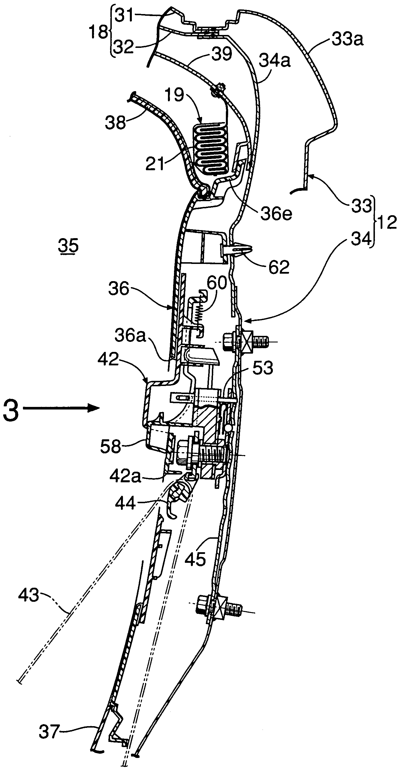
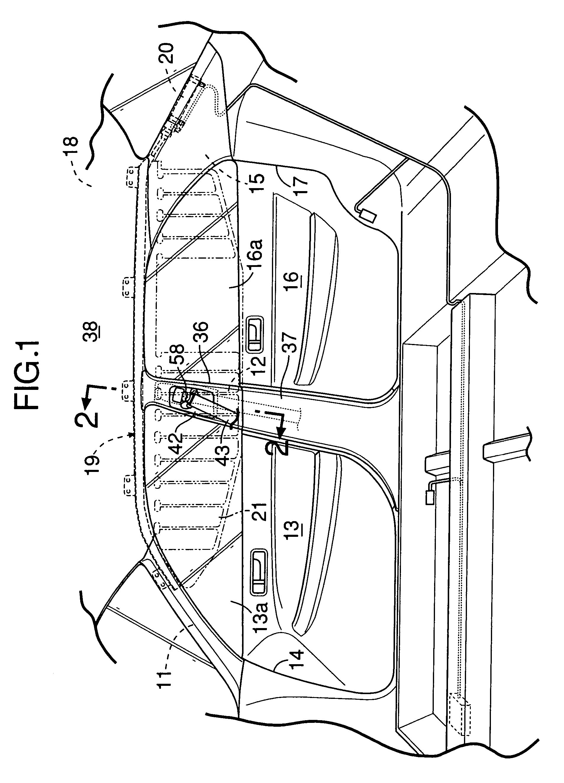
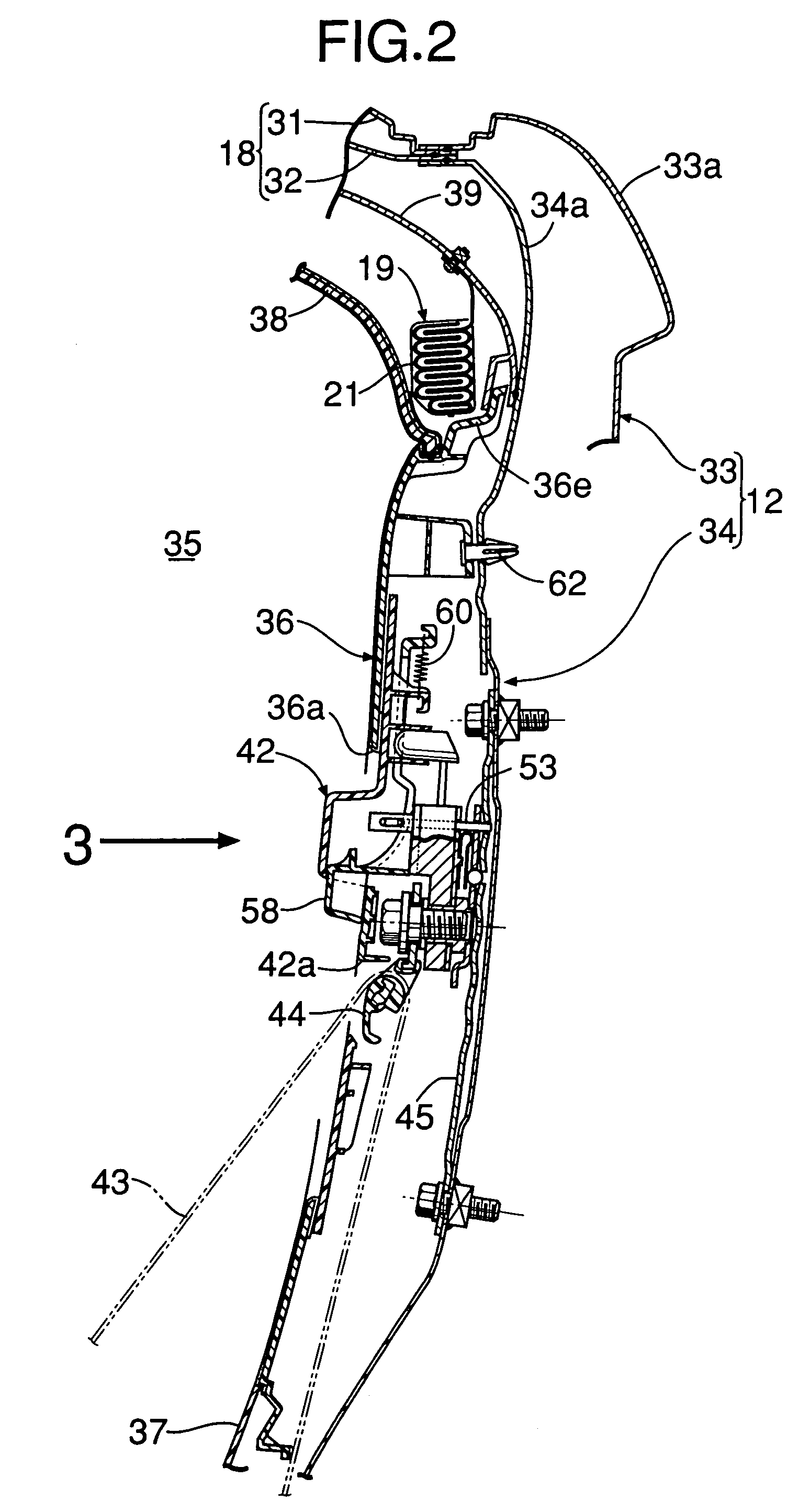
[0034]As shown in FIG. 1, on a side surface of a vehicle body of a vehicle, a door opening 14 in which a front door 13 is mounted is formed between a front pillar 11 and a center pillar 12, and a door opening 17 in which a rear door 16 is mounted is formed between the center pillar 12 and a rear pillar 15. An airbag module 19 is provided along a side edge of a roof 18 which extends from an upper end of the front pillar 11 to an upper end of the rear pillar 15. When acceleration of a predetermined value or higher is detected at a time of collision on the side surface of the vehicle or at a time of rolling over, an airbag 21 accommodated in the airbag module 19 is inflated by a high pressure gas which is supplied from an inflator 20 disposed inside the rear pillar 15, and deploys downward into a curtain shape from the side edge of the roof 18 so as to shield occupants seated on a front ...


PUM


Abstract

A lock releasing button is provided at a slide plate including a slip joint for slidably supporting a webbing for restraining an occupant to a seat. Locking of the slide plate to a center pillar is arranged to be released when the lock releasing button is pressed upward from below. Therefore, when an airbag presses to open a connecting portion between a roof lining and a pillar garnish and deploys downward at a time of collision of a vehicle, the lock releasing button is prevented from releasing the locking by being pressed by the airbag deploying downward. This prevents the situation in which the slip joint is moved downward together with the slide plate to loosen the webbing and thus a seat belt device cannot sufficiently exhibit an occupant restraining performance.

Description

BACKGROUND OF THE INVENTION[0001]1. Field of the Invention[0002]The present invention relates to a structure for adjusting a vertical position of a slip joint in a vehicle including an airbag device for deploying an airbag downward along an inner surface of a side portion of a vehicle compartment from a side edge of a roof, and a seat belt device in which a middle portion of a webbing is slidably guided by a slip joint provided at a pillar.[0003]2. Description of the Related Art[0004]Japanese Patent No. 3460636 discloses a seat belt device wherein a slide plate 52, to which a slip joint 51 for slidably guiding a webbing for restraining an occupant to a seat is fixed via an adjustable anchor 53, is supported along an inner surface of a center pillar garnish 22 to be movable up and down; projecting portions 22a and 52a triangular in section are formed at the center pillar garnish 22 or the slide plate 52 above the slip joint 51; and an airbag 31 which is deploying is guided with the p...

Claims


Application Information

Patent Timeline
Patent Type & Authority Patents(United States)
IPC IPC(8): B60R22/24B60R21/18B60R21/20B60R21/213B60R22/00B60R22/18B60R22/20
CPCB60R21/213B60R22/203
Inventor UNO, KOJIIKEDA, KOJIKAJIWARA, HIDEKINISHIZAKA, MITSUHIROSEKIGUCHI, NOBUMOTO
Owner HONDA MOTOR CO LTD
Why Eureka
Try Eureka