Wide-spread impeller spreader for harvesting combine

a technology of harvesting combine and spreader, which is applied in the direction of mowers, agricultural tools and machines, and can solve the problems of crop residue accumulation, crop residue accumulation, and inability to achieve a wide-spread distribution of crop material behind the combine, so as to prevent crop residue accumulation or clogging, and the effect of wide distribution width

a technology of harvesting combine and spreader, which is applied in the direction of mowers, agricultural tools and machines, and can solve the problems of crop residue accumulation, crop residue accumulation, and inability to achieve a wide-spread distribution of crop material behind the combine, so as to prevent crop residue accumulation or clogging, and the effect of wide distribution width

US7331855B2Active Publication Date: 2008-02-19DEERE & CO

Image

  • Wide-spread impeller spreader for harvesting combine
  • Wide-spread impeller spreader for harvesting combine
  • Wide-spread impeller spreader for harvesting combine

Examples


Embodiment Construction

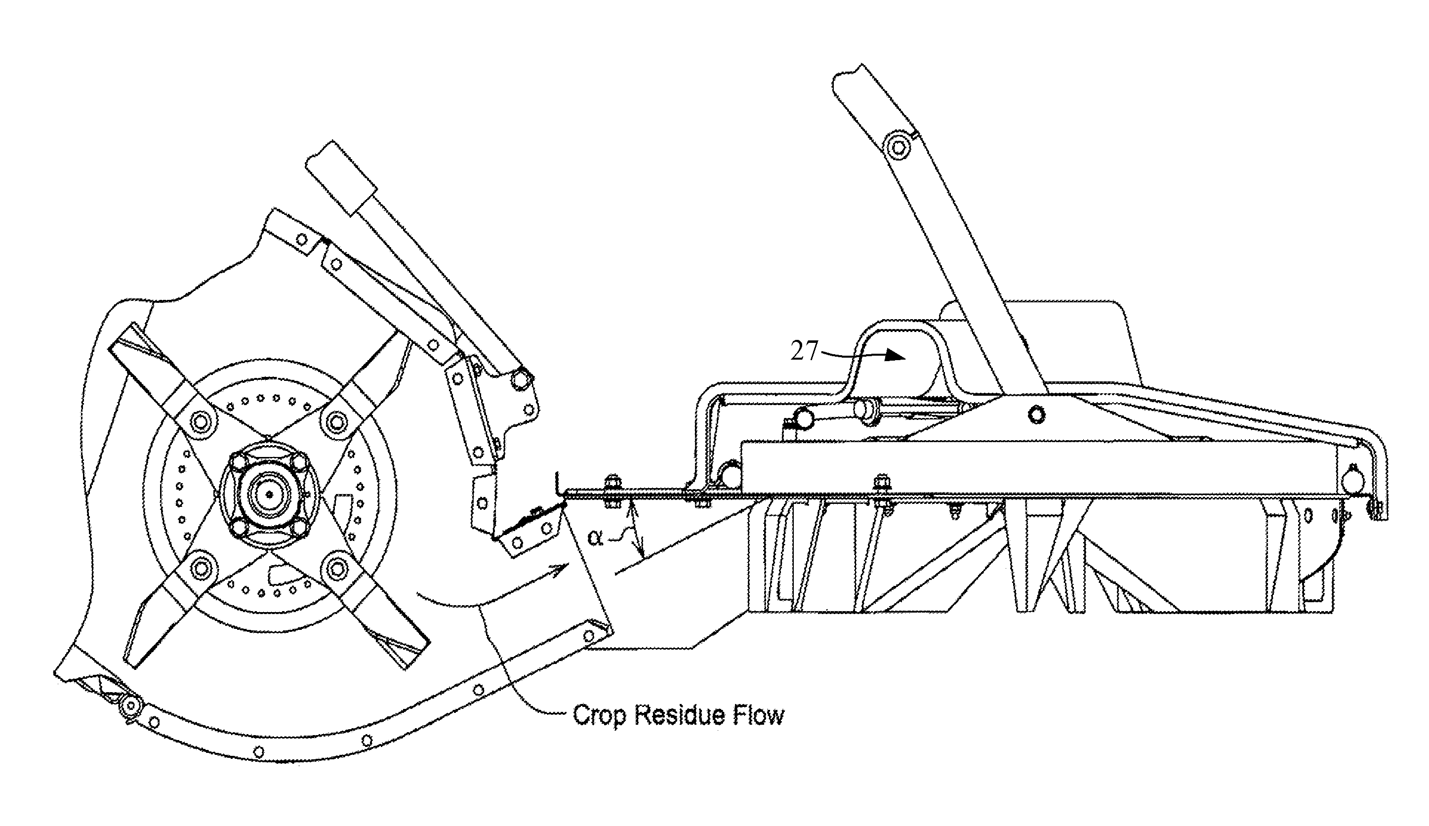
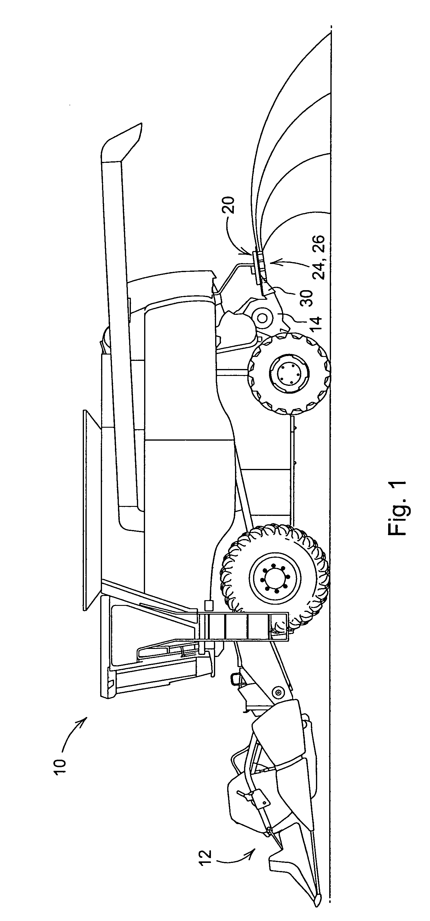
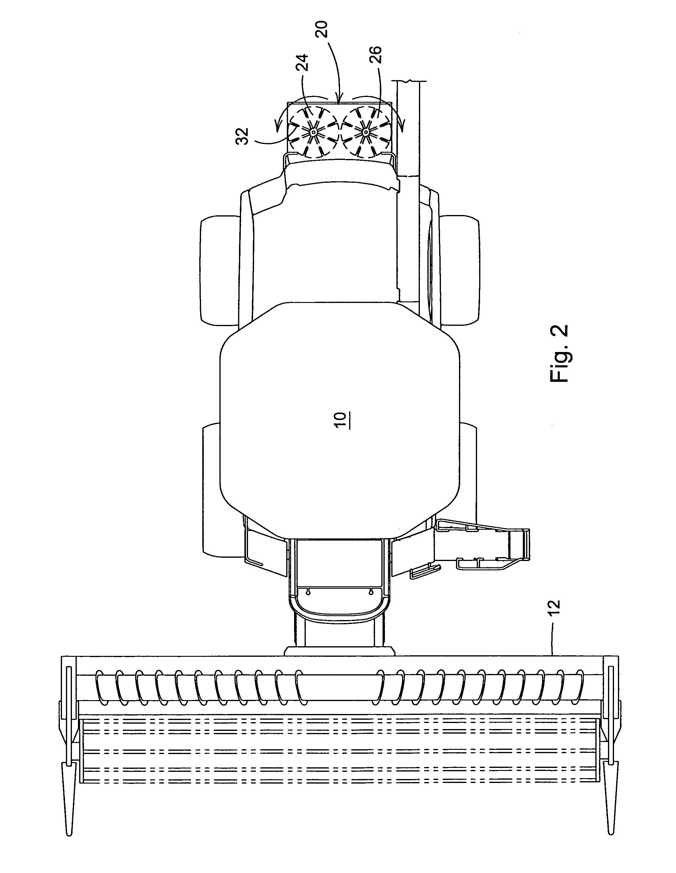
[0017]FIG. 1 illustrates a combine 10 commonly used in grain farming to harvest a variety of crops. As a combine 10 moves through a field during a harvesting operation, the ripened crop is cut from the field by a header 12 at the front of the combine 10. The crop is then transferred into threshing and separating assemblies (not shown) within the combine 10, where grain is removed from the crop material. The grain is transferred and stored in a hopper (not shown) onboard the combine 10 until it can be off-loaded for transport. The crop material other than grain, which is referred to herein as crop residue, is further processed or chopped, and then broadcast over a wide area behind the combine 10 by a spreader 20 attached to the rear of the combine 10. For greater broadcast widths, spreaders 20 comprised of counter-rotating impellers 24 and 26 can be employed for this task.

[0018]The spreader 20 comprises a right-side impeller 24, and a left-side impeller 26, that counter-rotate on par...


PUM


Abstract

A chopper and wide-spread impeller spreader that feeds crop residue from the chopper into the spreader at a specific upward angle to more fully utilize the momentum the crop residue achieves in the chopper. The spreader incorporates air intake holes and air fins above the impellers to keep crop residue moving through the impellers without plugging of discharge material. The chopper propels the residue upwardly into the spreader resulting in a wide-spread broadcast, while preventing crop residue from plugging the spreader.

Description

CROSS-REFERENCE TO RELATED APPLICATION[0001]This application claims priority to U.S. provisional patent application 60 / 700,000 titled “Wide Spread Impeller Spreader for Harvesting Combine” filed on Jul. 15, 2005, and having at least one inventor in common with the present application.FIELD OF THE INVENTION[0002]The present invention relates to a mechanism for spreading crop residue from a harvesting combine, and more particularly to a chopper with an impeller-type spreader that has dual rotating circular spreader disks.BACKGROUND OF THE INVENTION[0003]A combine is a machine that is used in grain farming to harvest a variety of crops from a field. Combines are typically self-propelled, but some are also towed and powered by tractors. As a combine moves through a field during a harvesting operation, the ripened crop is cut from the field by a header at the front of the combine. The crop is then transferred into threshing and separating assemblies within the combine, where grain is rem...

Claims


Application Information

Patent Timeline
19 Feb 2008
Publication
US7331855B2
IPC
A01F12/40
CPC
A01D41/1243; A01F12/40
Inventors
JOHNSON, PETER; PEARSON, MARK