Supercharge Your Innovation With Domain-Expert AI Agents!

Composite planetary device

a planetary roller and composite technology, applied in the direction of gearing, gearing details, hoisting equipment, etc., can solve the problems of backlash and meshing noise, unsuitable positioning mechanism, inability to transmit a large torque, etc., to achieve the effect of efficient increase of the output torque of the planetary roller mechanism

Active Publication Date: 2008-02-19
HARMONIC DRIVE SYST IND CO LTD
View PDF7 Cites 1 Cited by
  • Summary
  • Abstract
  • Description
  • Claims
  • Application Information

AI Technical Summary

Benefits of technology

The present invention provides a composite planetary device that can efficiently increase the output torque of a planetary roller mechanism. The device includes a planetary gear mechanism and a planetary roller mechanism, which are integrally rotated around a common rotating center axis or can be fixed concentrically. The device also includes a sun roller and a planetary roller that rotate integrally around the same axis, and a ring roller that rotates integrally around the same axis or can be fixed concentrically. The device has slippage between the sun roller and the planetary roller, and between the planetary roller and the ring roller, which can be made the same. The device can achieve these slippage ratios by combining gears of the planetary gear mechanism and making the radius of the sun roller and the planetary roller larger than the radius of the working pitch circle of the sun gear and the planetary gear meshing with the internal gear, respectively. The device has superior performance in the low torque region of the planetary gear mechanism and reduces meshing noise. It also increases torsional stiffness in the low torque region of the planetary gear mechanism.

Problems solved by technology

As disclosed in these patent documents, a planetary gear speed reducer can transmit a large torque but has the problems of backlash and meshing noise.
However, it continually produces slippage, which makes it unsuitable for positioning mechanisms and the like, and also has the problem of not being able to transmit a large torque.
However, conventional composite planetary devices have the following problems.
Thus, the roller drive forces generated between the rollers cancel each other out, making it impossible to obtain a large output torque.

Method used


Image

  • Composite planetary device
  • Composite planetary device
  • Composite planetary device

Examples


example

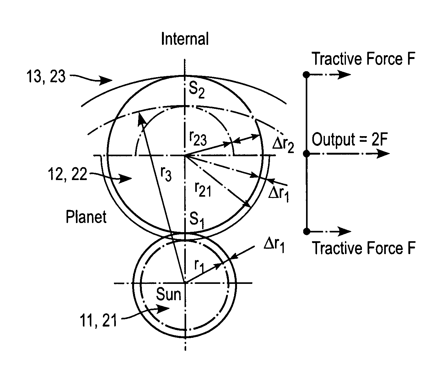
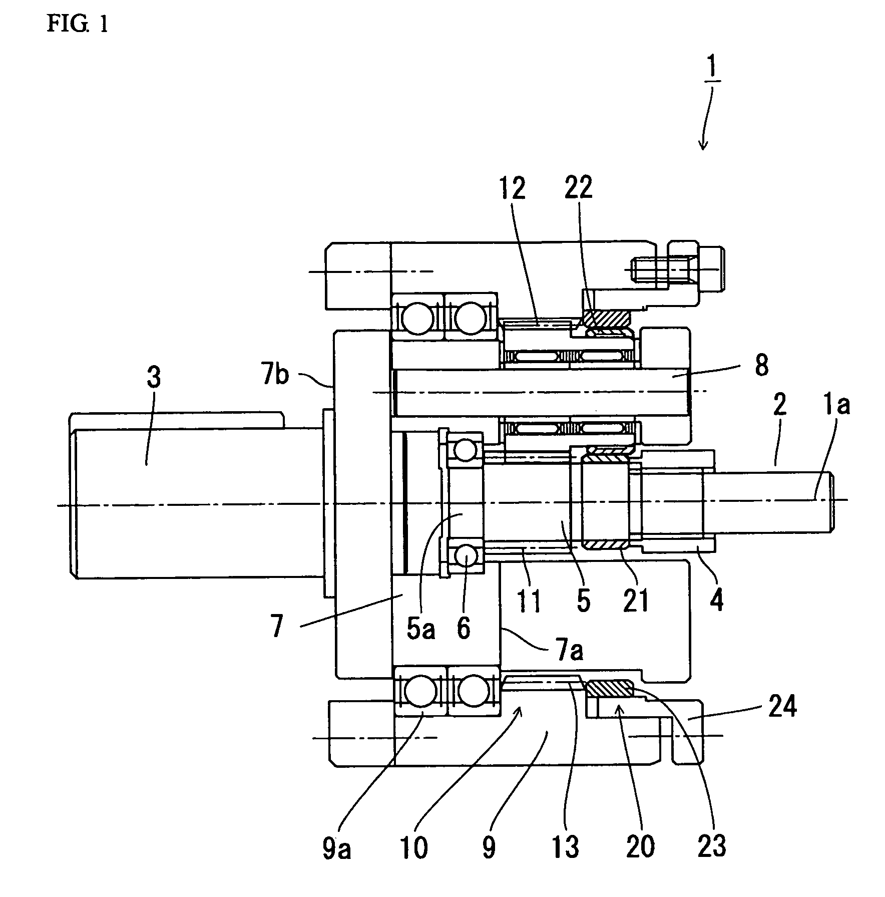
[0050]An example of the composite planetary speed reduction device 1 having the above configuration will now be described. A sun gear having a number of teeth Za=24, planetary gears each having a number of teeth Zb=36, and an internal gear having a number of teeth Zd=96 is a general example of a tooth-number combination used in planetary gear speed reduction mechanisms. In this case, the speed reduction ratio Ug is 1 / 5. Because addendum modification coefficient of zero can be used for the gears, enabling the use of standard gears and eliminating the task of design, this combination of teeth numbers is extensively used. However, in this tooth-number combination, the value of j defined by the above equation (1) is zero, so slippage ratios s1 and s2 between rollers are also zero, so a large tractive force cannot be obtained (see the schematic drawing of FIG. 3).

[0051]In this example, the number of teeth of the planetary gear 12 is reduced by one, to Zb=35, and j=1. In this case, the re...


PUM


Abstract

A composite planetary speed reduction device (1), wherein gears (11), (12), and (13) and rollers (21), (22), and (23) forming a planetary gear speed reduction mechanism (10) and a planetary roller speed reduction mechanism (20) are integrally rotated around a common rotating center axis, respectively. The radius of the sun roller (21) is larger by Δr1 than the radius r1 of the working pitch circle of the sun gear (11), the radius r21 of the working pitch circle of the planetary gear (12) meshing with the sun gear (11) and the radius r23 of the working pitch circle of the planetary gear (12) meshing with an internal gear (13) are different from each other, and the radius of the planetary roller (22) is smaller by Δr1 than the radius r21 of the working pitch circle of the planetary gear (12). Thus, a slippage ratio s1 between the sun roller (21) and the planetary roller (22) and a slippage ratio s2 between the planetary roller (22) and the ring roller (23) are made equal to each other, and a large output torque can be provided from the planetary roller speed reduction mechanism (20).

Description

TECHNICAL FIELD[0001]The present invention relates to a composite planetary device wherein gears forming a planetary gear mechanism and a planetary roller mechanism are each integrally rotated around a common rotating center axis. It particularly relates to a composite planetary device having a planetary roller mechanism that provides high output torque.BACKGROUND ART[0002]Composite planetary devices comprised of a planetary gear mechanism and planetary roller mechanism are disclosed by JP A 9-168910 and JP A 2002-213566, for example. As disclosed in these patent documents, a planetary gear speed reducer can transmit a large torque but has the problems of backlash and meshing noise. A planetary roller speed reducer has zero backlash and low noise. However, it continually produces slippage, which makes it unsuitable for positioning mechanisms and the like, and also has the problem of not being able to transmit a large torque. A composite planetary device can mutually compensate for t...

Claims


Application Information

Patent Timeline
Patent Type & Authority Patents(United States)
IPC IPC(8): F16H57/12F16H1/28F16H13/08F16H37/02
CPCF16H1/28F16H13/06F16H57/02004F16H37/021Y10T74/19623F16H57/0006
Inventor HORI, KOHEI
Owner HARMONIC DRIVE SYST IND CO LTD
Features
  • R&D
  • Intellectual Property
  • Life Sciences
  • Materials
  • Tech Scout
  • Unparalleled Data Quality
  • Higher Quality Content
  • 60% Fewer Hallucinations
Learn More