Cooling and handling of reaction torque for an axial flux motor

a technology of reaction torque and axial flux, which is applied in the field of electric motors, can solve the problems of limiting the sizing and power rating of motors, affecting the reliability of motors,

Inactive Publication Date: 2008-02-19
GM GLOBAL TECH OPERATIONS LLC
View PDF48 Cites 59 Cited by
  • Summary
  • Abstract
  • Description
  • Claims
  • Application Information

AI Technical Summary

Problems solved by technology

Heat dissipation is the limiting factor in motor sizing and power ratings.
While such systems are functional, they suffer from higher weight, lower reliability and lower efficiency due to the mechanical drive-line (gears, differentials, transmissions, etc.) between the motor(s) and the wheels.

Method used


Image

  • Cooling and handling of reaction torque for an axial flux motor
  • Cooling and handling of reaction torque for an axial flux motor
  • Cooling and handling of reaction torque for an axial flux motor

Examples


case 1 (

Case 1(M*indexlow)

[0099]Mref is set to Mhigh and Idsat+is set to zero. With these settings the error signal to the PI block 196 is positive and the output of voltage loop 186 is zero since the upper saturation limit in the saturation block 198 is set to zero. Thus voltage loop 186 is deactivated. The negative saturation limit of block 198 has no consequence, however, for convenience it is set to −K2|Id*|.

case 2 (

Case 2(M*index≧Mlow and M*index high

[0100]Mref is set to Mindex. The upper and the lower saturation limits in block 198 are set to K1|Id*|and −K2|Id*| respectively. These settings activate voltage loop 186. Voltage loop 186 loop is activated when M*index exceeds the lower limit Mlow. This lower limit can be set to any value. Typically when current regulator 160 is operating in the linear region (e.g., M*index182 has adequate voltage margin and help from voltage loop 186 is generally not required. Therefore, the lower limit Mlow may be set at the transition value between the linear and the non-linear region or slightly lower. This allows a smooth transition from the linear to the non-linear region.

[0101]The d-axis current command I*d is calculated in block 162 to maximize the system performance while properly utilizing the bus voltage. Therefore, ideally under steady state condition M* index should closely match with Mindex and no help would be needed from voltage loop 186. In other ...

case 3 (

Case 3(M*index≧Mhigh)

[0102]If M*index exceeds a certain pre-defined limit Mhigh(see also FIG. 17), then Mref is set to Mhigh. The Mhigh value basically sets the upper limit of operation in the overmodulation region. In our experiment we set this value to the 95% of six-step operation. Voltage control to full six-step would, however, not be recommended since the voltage margin between six-step operation and 95% of six-step operation is needed by the current loop to take care of any transient operation. The saturation limits of block 198 are therefore kept unchanged from the values of case 2.

[0103]The overall operation of control system function 160 of FIGS. 20A-B (carried out by system 500 of FIG. 22) is now described. The voltage loop of control function 160 comprising functions 188, 190, 192, 194, 196, 198 and the decision table described in Table I, directly modify the d-axis current of the machine to control the machine voltage. Based on torque command T*, machine speed ωr and DC...


PUM


Abstract

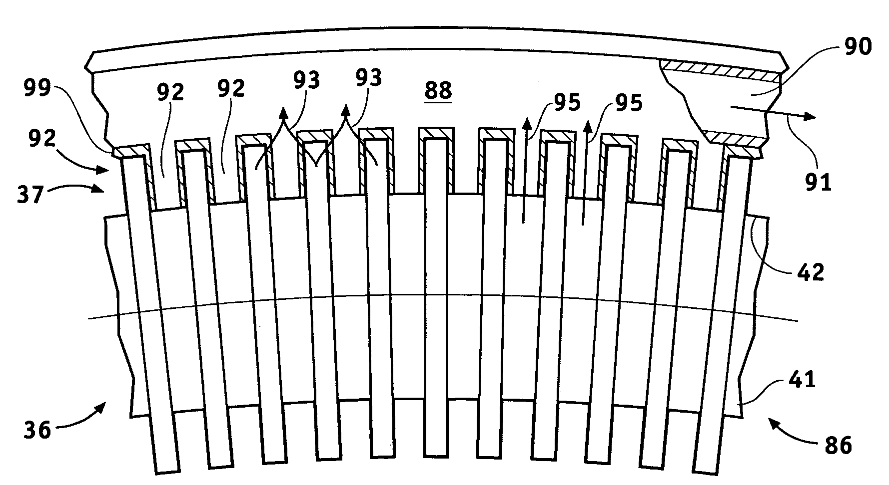
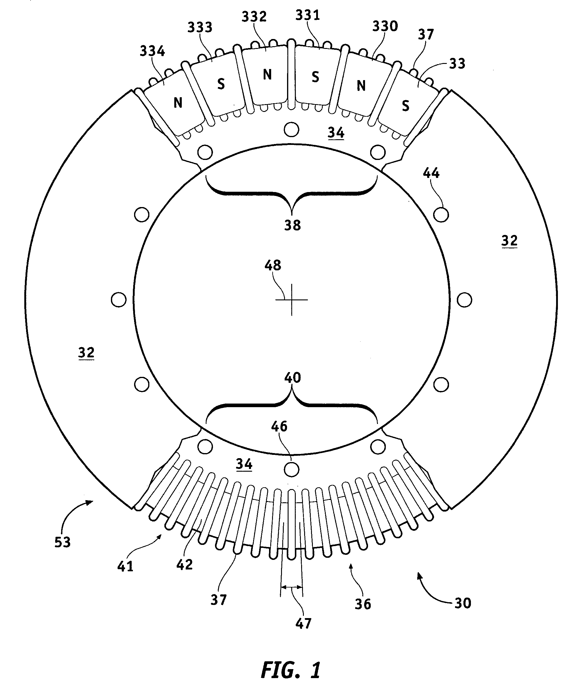
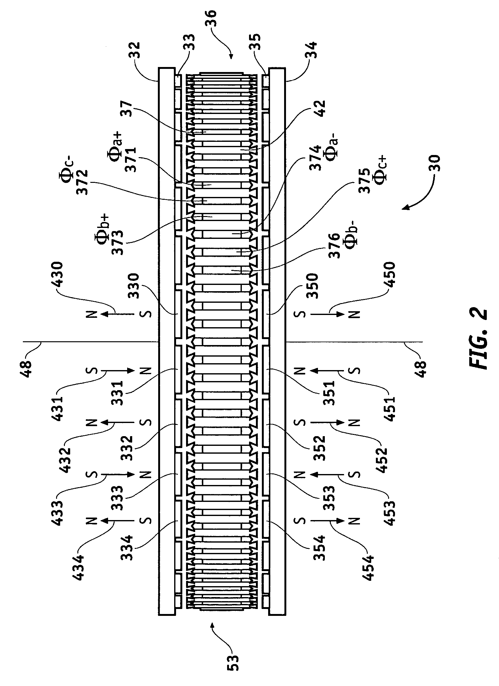
Methods and apparatus are provided for an axial electric motor. The apparatus comprises, a stator having coils thereon for producing a magnetic field, a rotor rotated by the magnetic field, an output shaft coupled to the rotor, and a ring incorporating a coolant channel circumferentially engaging the stator for absorbing heat and reaction torque from the stator. It is preferable that that the ring have inwardly extending teeth that mesh with the coils on the stator. The space between the teeth and the coils is preferably filled with a substantially solid thermally conductive material to transmit stator reaction torque to the teeth and cool the stator. The coils are preferably formed from a flat ribbon a portion of whose principal surface is perpendicular to the teeth. A supporting frame is desirably fixedly coupled to the ring and rotatably coupled to the output shaft.

Description

CROSS-REFERENCES TO RELATED APPLICATIONS[0001]This application claims the benefit of U.S. Provisional Applications Nos. 60 / 494,249; 60 / 494,250; and 60 / 494,251, all filed on Aug. 11, 2003.TECHNICAL FIELD[0002]The present invention generally relates to an electric motor. More specifically, the present invention relates to a method and apparatus to cool an electric motor and handle the reactive torque of the motor.BACKGROUND[0003]An electric motor may be described as generally comprising a stator and a rotor. The stator is fixed in position and the rotor moves relative to the stator. In AC or axial motors, the stator is typically the current carrying component of the motor generating a magnetic field to interact with the rotor. The rotor in an AC or axial motor may comprise a squirrel cage or a magnetic rotor. The field generated by the stator will propel or rotate the rotor via a magnetic field relative to the stator.[0004]The operation of an electric motor generates heat in the form ...

Claims


Application Information

Patent Timeline
Patent Type & Authority Patents(United States)
IPC IPC(8): H02K9/00H02K1/18H02K1/27H02K3/46H02K3/50H02K5/20H02K7/14H02K9/22H02K21/24
CPCH02K1/182H02K3/46H02K5/20H02K9/22H02K21/24H02K1/2793H02K7/14H02P21/00B60L1/02B60L3/0061B60L15/025B60L2220/14B60L2220/16B60L2240/421B60L2240/423B60L2240/425B60L2240/427B60L2240/429B60L2270/145B60L2220/50Y02T10/64H02K5/207H02K9/227H02K5/203H02K9/223H02K1/2798
Inventor WARD, TERENCE G.RAHMAN, KHWAJA M.NAGASHIMA, JAMES M.CRESCIMBINI, FABIOCARICCHI, FEDERICOLUCCHI, GIORGIO
Owner GM GLOBAL TECH OPERATIONS LLC
Why Eureka
Try Eureka