
Liquid-crystal display apparatus and electronic device

a liquid crystal display and display device technology, applied in the direction of static indicating devices, lighting and heating devices, instruments, etc., can solve the problems of insufficient color reproducing capability of such related-art liquid crystal display apparatus, inability to obtain clear color of each pixel, and inability to use cold cathode-ray tubes in portable electronic devices. , to achieve the effect of reducing power consumption, widening color reproducing range, and reducing power consumption

Inactive Publication Date: 2008-02-19
SONY CORP
View PDF8 Cites 32 Cited by
  • Summary
  • Abstract
  • Description
  • Claims
  • Application Information

AI Technical Summary

Benefits of technology

[0026]Further, the present invention intends to provide a liquid-crystal display apparatus in which electric power can be consumed more efficiently so that a time period in which the liquid-crystal display apparatus is driven can be extended.
[0027]Further, the present invention intends to provide a liquid-crystal display apparatus in which color display can be made clear, if necessary, so that viewers are able to watch a beautiful picture.
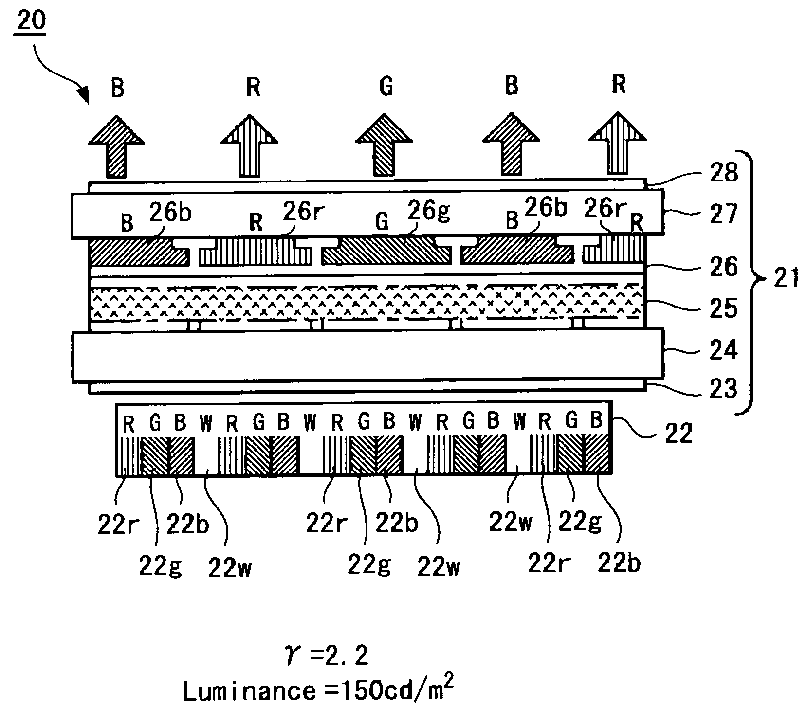
[0034]According to the liquid-crystal display apparatus and the electronic device of the present invention, the illuminance detecting means compares the ambient illuminance of the liquid-crystal panel with the reference illuminance, and the light source control means switches the first and second light sources in response to the compared result of the illuminance, whereby the first light source for emitting white light is driven to decrease power consumption when a viewer watches the liquid-crystal panel in the outdoor with large illuminance or when a viewer watches the liquid-crystal panel over a long period of time. Whereas, when a user watches the liquid-crystal panel in the indoor with small illuminance, the second light source for emitting more than two lights containing white light is driven to widen a color reproducing range. As a result, the viewer is able to visually confirm clear and beautiful colors.
[0035]According to the present invention, it is possible to realize the liquid-crystal display apparatus and the electronic device in which the light source is switched in response to the ambient illuminance of the liquid-crystal panel and the two light sources are selectively used in response to a use so that electric power consumption can be consumed more efficiently, a time in which the liquid-crystal display apparatus and the electronic device are driven in use can be extended, color image can be made clear if necessary, thus to make it possible for viewers to visually confirm beautiful pictures.

Problems solved by technology

However, since a high voltage is required to drive the cold cathode-ray tube, in the actual situations, the cold cathode-ray tube is hardly used in portable electronic devices because portable electronic devices tend to regard small power consumption as being important.
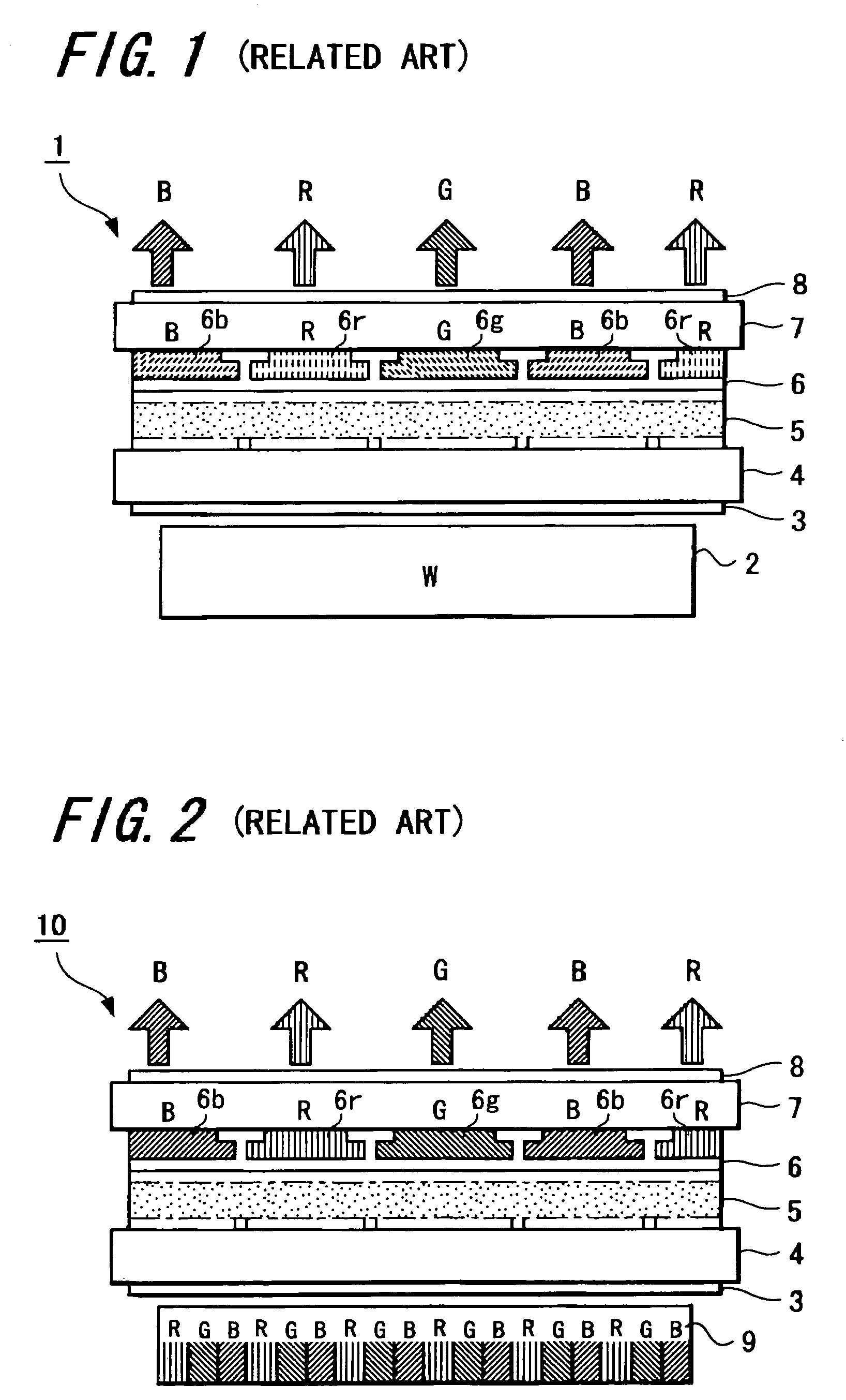
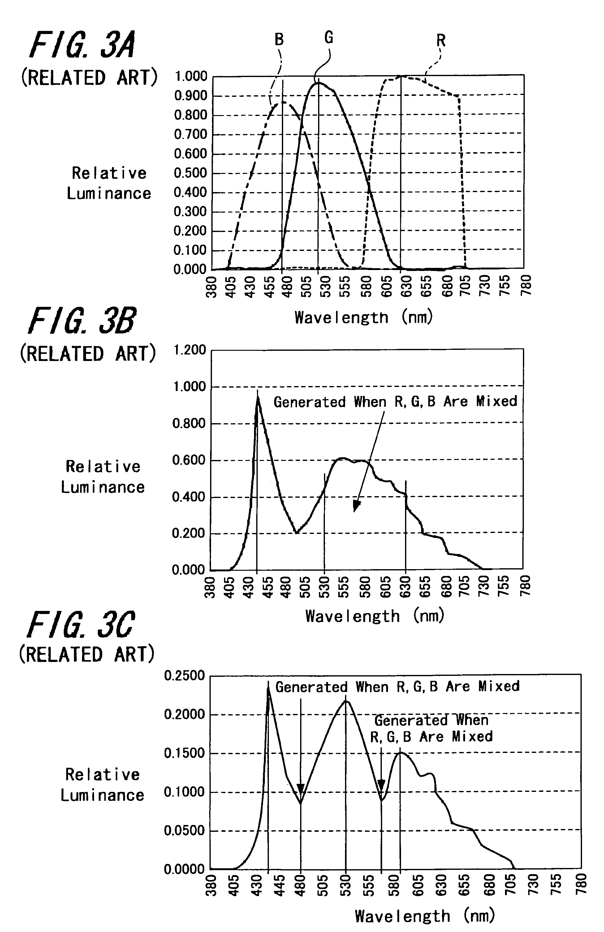
Therefore, because light-emissions of red (R), green (G) and blue (B) should be superimposed upon each other with a time lag, it is not possible to obtain a clear color of each pixel and hence a color reproducing capability of such related-art liquid-crystal display apparatus is not sufficient.
Also, in the liquid-crystal display apparatus described in the above-mentioned Cited Patent Reference 2, since three colors of the backlight light source which emits lights of three primary colors should be emitted sequentially, many colors are expressed at one pixel by changing transmittance of each color in one pixel in response to a pixel signal and one dot of color display is displayed by one pixel a clear color may not be obtained at each pixel and a color reproducing capability is not sufficient similarly as described above.

Method used


Image

  • Liquid-crystal display apparatus and electronic device
  • Liquid-crystal display apparatus and electronic device
  • Liquid-crystal display apparatus and electronic device

Examples


first embodiment

[0064]FIGS. 6 to 25 are diagrams to which reference will be made in explaining the embodiments of the present invention. More specifically, FIG. 6 is an explanatory diagram showing a schematic arrangement of the liquid-crystal display apparatus according to the present invention. FIG. 7 is a block diagram showing a schematic arrangement of an electronic device that uses the liquid-crystal display apparatus shown in FIG. 6. FIGS. 8 and 9 are block diagrams showing the embodiments of power supply circuits for use with the liquid-crystal display apparatus shown in FIG. 6. FIGS. 10A, 10B, 10C and 10D are explanatory diagrams showing examples of combinations of respective color light-emitting diodes constructing the backlight of the liquid-crystal display apparatus shown in FIG. 6, respectively. FIGS. 11A, 11B and 11C are explanatory diagrams showing examples of arrangements of the light-emitting diodes and the packages constructing the backlight of the liquid-crystal display apparatus s...

second embodiment

[0065]FIG. 16 is an explanatory diagram showing a schematic arrangement of the liquid-crystal display apparatus according to the present invention. FIG. 17 is a block diagram showing the embodiment of a power supply circuit for use with the liquid-crystal display apparatus shown in FIG. 16. FIGS. 18A and 18B are explanatory diagrams showing the embodiments of schematic arrangements of white light-emitting diodes constructing the backlight of the liquid-crystal display apparatus shown in FIG. 16, respectively. FIGS. 19A, 19B and 19C are explanatory diagrams showing examples of arrangements of white light-emitting diodes constructing the backlight of the liquid-crystal display apparatus shown in FIG. 16, respectively. FIGS. 20A, 20B and 20C are explanatory diagrams showing examples in which white light-emitting diodes constructing the backlight of the liquid-crystal display apparatus shown in FIG. 16 are energized, respectively. FIGS. 21, 22 and 23 are flowcharts showing examples of c...


PUM

PropertyMeasurementUnit
wavelengthaaaaaaaaaa

Abstract

A liquid-crystal display apparatus includes a liquid-crystal panel (25) having a color filter (26), a W light-emitting diode (22w) for irradiating white light to the liquid-crystal panel (25), RGB light-emitting diodes (22r, 22g, 22b) for irradiating lights of more than two colors containing white to the liquid-crystal panel (25), a luminance sensor (44) for detecting ambient illuminance of the liquid-crystal panel (25) to output a detected signal and a control unit (41) for switching the W light-emitting diode (22w) and the RGB light-emitting diodes (22r, 22g, 22b) based on the detected signal from the luminance sensor (44). In a related-art liquid-crystal display apparatus, since lights of red (R), green (G) and blue (B) are emitted with a time lag and superimposed upon each other so that a clear color may not be obtained in each pixel, thus resulting in insufficient color reproducing capability. According to the present invention, these defects encountered with the related art can be obviated.

Description

CROSS-REFERENCE TO RELATED APPLICATIONS[0001]The present application claims priority from Japanese Patent Application Nos. JP 2005-138663 filed on May 11, 2005 and JP 2006-044304 filed on Feb. 21, 2006 the disclosures of which are hereby incorporated by reference herein.BACKGROUND OF THE INVENTION[0002]The present invention relates to a liquid-crystal display apparatus including a liquid-crystal panel having a color filter and its light source and an electronic device, and particularly to a liquid-crystal display apparatus including a first light source for emitting light of white color (first white light) as a backlight and a second light source for emitting light of white color different from the first white color (second white light) such that the first and second light sources can be switched in response to ambient illuminance and an electronic device including the liquid-crystal display apparatus.[0003]The Cited Patent Reference 1, for example, has so far described this kind of...

Claims


Application Information

Patent Timeline
Patent Type & Authority Patents(United States)
IPC IPC(8): G02F1/1335G09G3/36G09G5/00
CPCG02F1/133621G09G3/3413G09G3/3611G09G2320/0626G09G2320/0666G09G2330/021G09G2360/144G02F1/133
Inventor NAKANO, MINORUSAIKI, KUNIHITO
Owner SONY CORP
Learn More