Methods for the use and manufacture of infrared position sensing detector focal plane arrays for optical tracking

Active Publication Date: 2008-02-19
OCEANIT LAB
View PDF3 Cites 14 Cited by
  • Summary
  • Abstract
  • Description
  • Claims
  • Application Information

AI Technical Summary

Benefits of technology

[0016]Oceanit Laboratories, Inc.'s Multi-target Optical Sensor Technology (MOST) is a sensor technology and method for ballistic missile defense, battle space-awareness enhancement and multiple-target discrimination. MOST integrates key components of successful Oceanit technologies to create a unique optical sensor capability that provides highly accurate positional metrics with wide field-of-view and at high temporal bandwidth, on a fast-tracking platform. These are described in applicant's co-pending applications: Ser. No. 10/128,433 (ARRAY OF LATERAL

Problems solved by technology

Some of these methods, even if available toda

Method used


Image

  • Methods for the use and manufacture of infrared position sensing detector focal plane arrays for optical tracking
  • Methods for the use and manufacture of infrared position sensing detector focal plane arrays for optical tracking
  • Methods for the use and manufacture of infrared position sensing detector focal plane arrays for optical tracking

Examples


Embodiment Construction

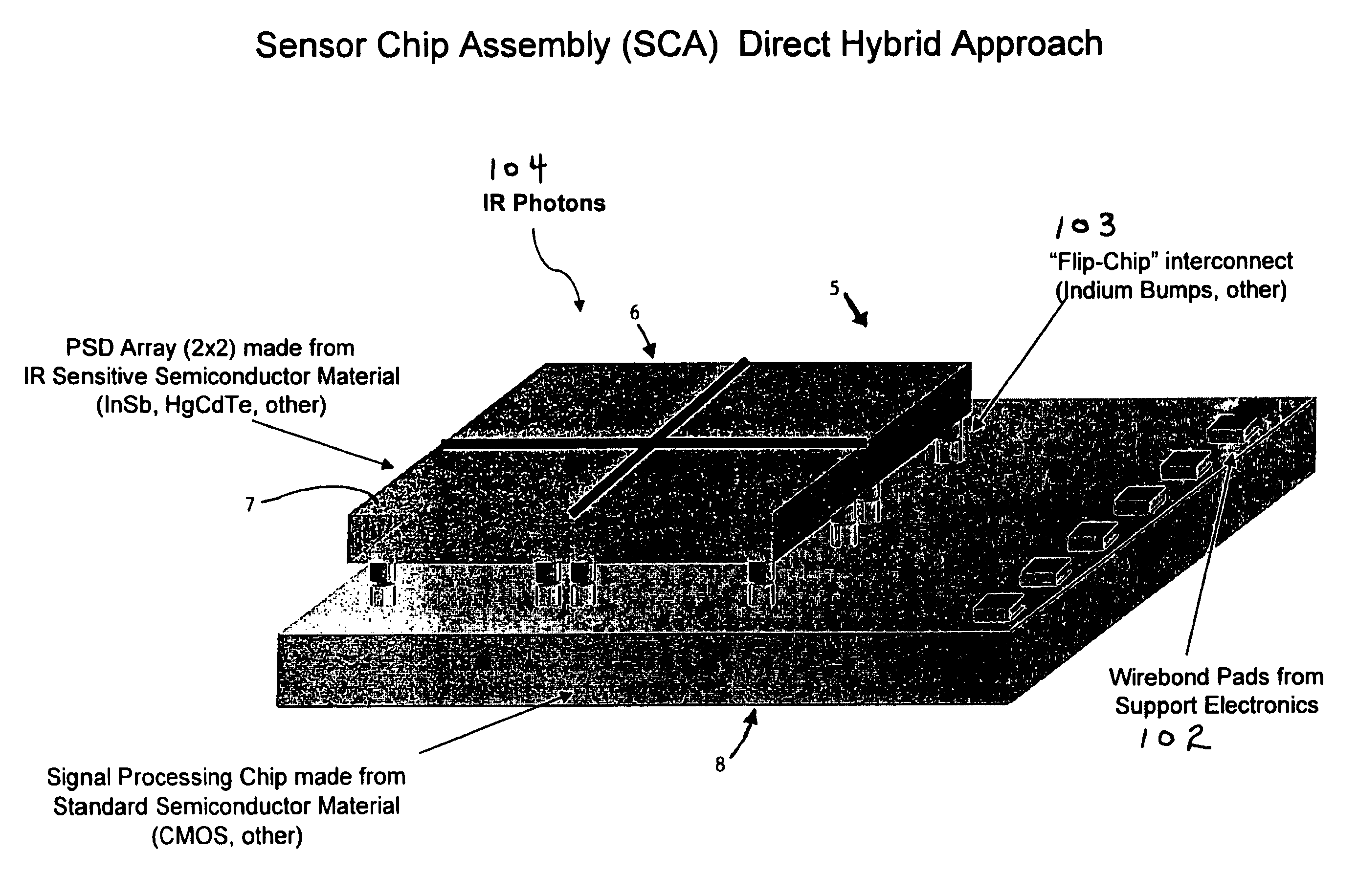
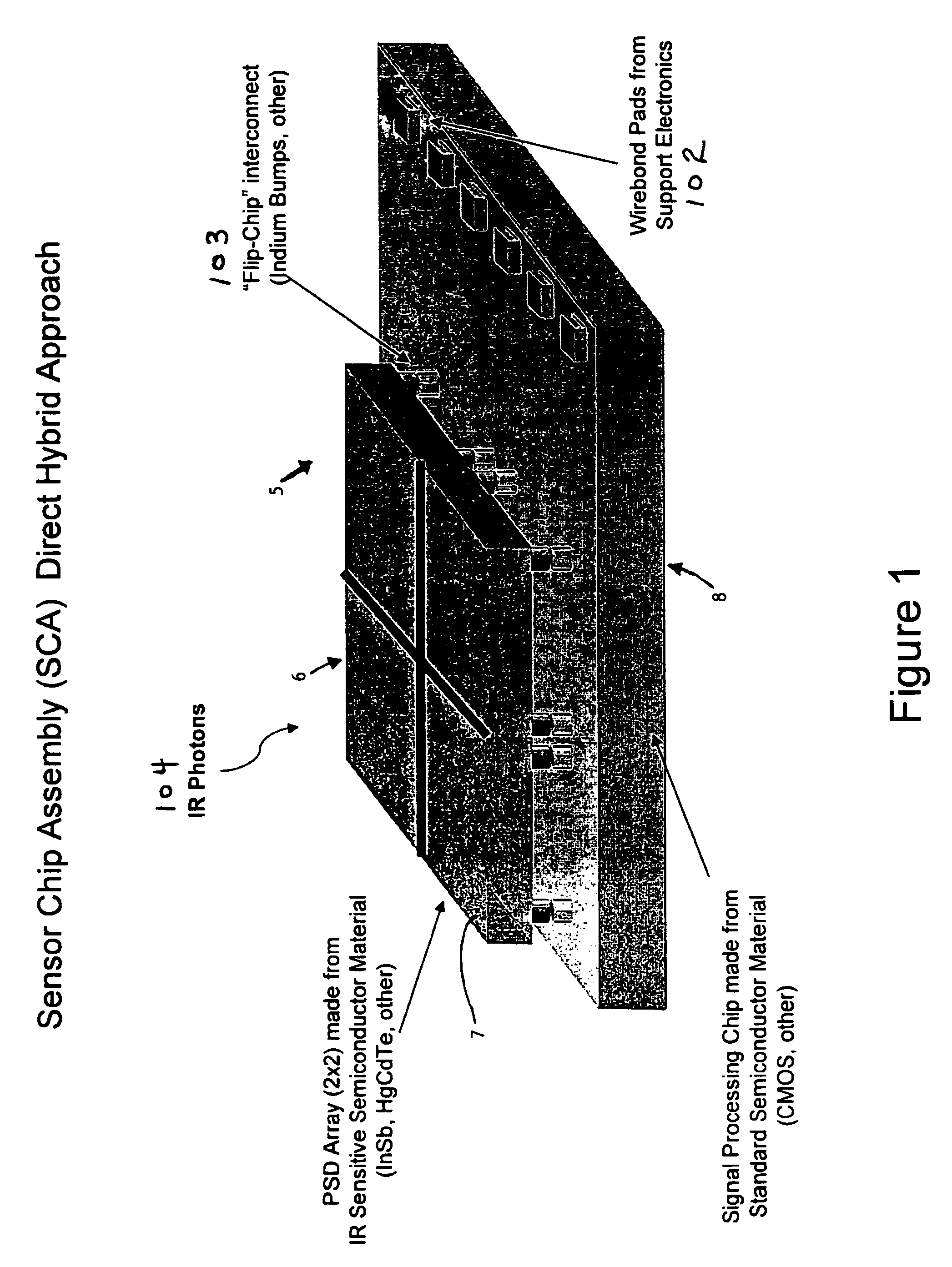
[0028]FIG. 1 shows an exemplary Sensor Chip Assembly (SCA). The focal plane array 5 is constructed as a semiconductor chip sandwich—one slice 6 contains the array of PSDs 7 made from IR sensitive semiconductor material, and the other slice 8 contains Trans Impedance Amplifiers (TIAs)—and associated on-chip signal processing elements from an electronic semiconductor material. The SCA resembles those made for pixelized imaging IR SCA focal planes, but the configuration and implementation of which is for a PSD focal plane array. The use of these techniques assures that the PSD focal plane array possesses the required attributes.

[0029]The PSD Array 7 may be, but is not limited to, a 2×2 array made from IR sensitive semiconductor material. The IR sensitive semiconductor material may be, but is not limited to, INSB, HgCdTe or other similar materials. IR photons 104 strike the PSD Array 7. Flip-chip interconnects 103 connect the PSD array 7 with the signal processing chip 8. The flip-chip ...


PUM


Abstract

A Sensor Chip Assembly (SCA) contains a focal plane array constructed as a semiconductor chip sandwich. One slice contains an array of PSDs made from IR sensitive semiconductor material, and the other slice contains Trans Impedance Amplifiers (TIAs)—and associated on-chip signal processing elements from an electronic semiconductor material. The SCA resembles those made for pixelized imaging IR SCA focal planes, but the configuration and implementation of which is for a PSD focal plane array. The use of these techniques assures that the PSD focal plane array possesses the required attributes. Interconnect technology is widely available from most IR fabrication houses to connect the IR array with the TIA circuits.

Description

[0001]This application claims the benefit of U.S. Provisional Application No. 60 / 680,742, filed May 13, 2005, which is hereby incorporated by reference in its entirety.BACKGROUND OF THE INVENTION[0002]Tracking is a basic surveillance function that is important in numerous commercial and military applications. Increasingly, there is a requirement to augment, or even replace, the radar technology traditionally used for this task with optical tracking systems.[0003]Key applications include missile tracking for theater and national defense systems, battlefield defensive systems (e.g. sniper detection), homeland security defensive systems, and the like. However, the utility of existing optical tracking systems for these missions is limited by their speed, accuracy and detection capability.[0004]Needs exist for extending these limits to new operational regimes.SUMMARY OF THE INVENTION[0005]The present invention addresses the needs of prior systems. Position Sensing Detector (PSD) based Fo...

Claims


Application Information

Patent Timeline
IPC IPC(8): G01C5/00
CPCF41G3/147G01S3/781G01S3/784H01L31/02024H04N5/33
Inventor SCOTT, BASIL H.WOLFSHAGEN, RANDYBUCK, JEFF
Owner OCEANIT LAB
Why Eureka
Try Eureka