
Apparatus and method for inspecting defects

a technology of apparatus and defects, applied in the direction of optical investigation of flaws/contamination, semiconductor/solid-state device testing/measurement, instruments, etc., can solve the problems of insufficient consideration of a design capable of inspecting very small particle-like contamination, scratching, and other defects, and achieves a high-efficiency manufacturing line for substrates

Inactive Publication Date: 2008-02-19
HITACHI HIGH-TECH CORP
View PDF37 Cites 32 Cited by
  • Summary
  • Abstract
  • Description
  • Claims
  • Application Information

AI Technical Summary

Benefits of technology

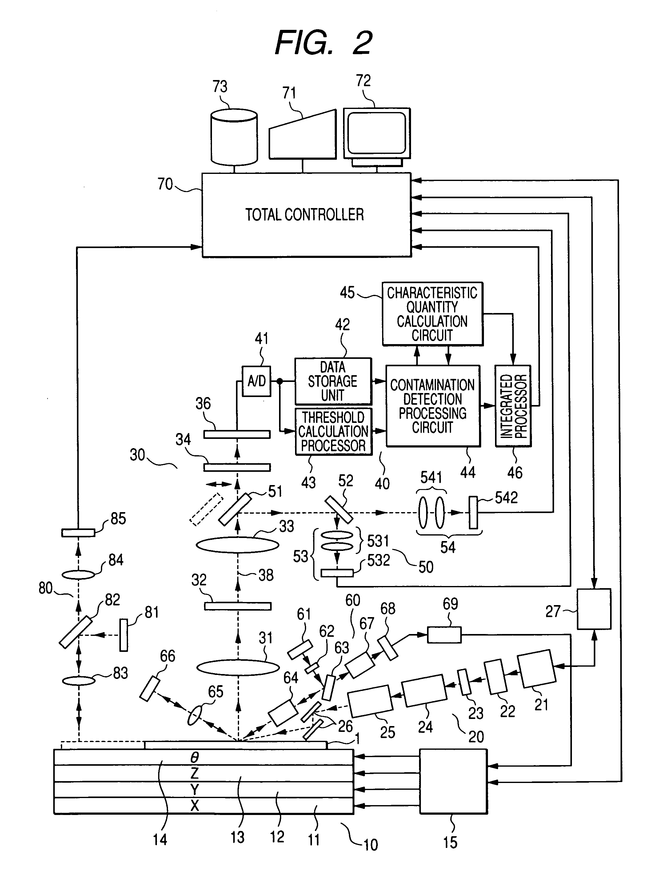
The present invention provides an apparatus and method for inspecting defects on various types of substrates with high accuracy and efficiency. The apparatus includes an irradiation optical system that guides a flux of beams emitted from a laser light source, and focuses the beam flux onto the substrate being inspected. A detection optical system uses an objective lens to converge reflected / scattered light from the substrate, and an image sensor to receive and detect the light. An image processor extracts a signal indicative of the defect, such as contamination. The apparatus can be used in a manufacturing line for substrates, allowing for efficient and effective defect inspection.

Problems solved by technology

In Patent Documents 1-7 outlined above, however, sufficient consideration has not been paid to a design capable of inspecting very small particle-like contamination, thin-film-like contamination, scratches, and other defects present on various types of substrates that is to be inspected, in a simple configuration.

Method used


Image

  • Apparatus and method for inspecting defects
  • Apparatus and method for inspecting defects
  • Apparatus and method for inspecting defects

Examples


Embodiment Construction

[0064]Hereunder, embodiments of the present invention will be described using the accompanying drawings.

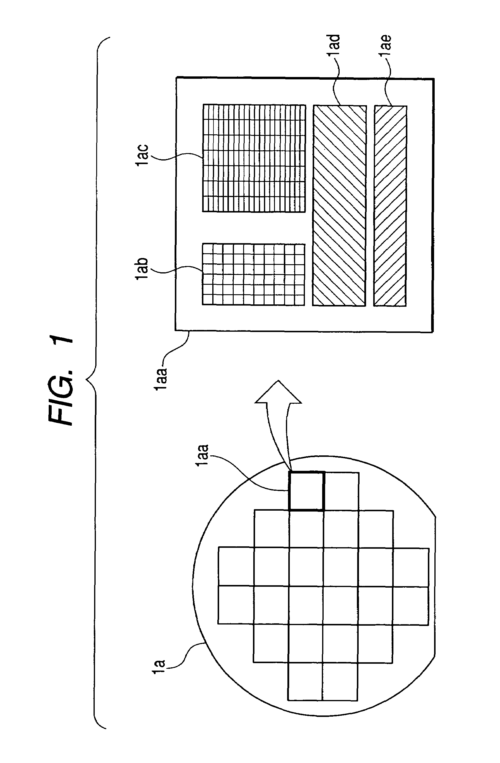
[0065]One possible kind of object 1 to be subjected to inspection of defects such as contamination, is a semiconductor wafer “1a” with chips “1aa” arrayed two-dimensionally at required spatial intervals (hereinafter, the object 1 is referred to as the inspection target 1). An interior of each chip “1aa” is mainly formed up by a register group region “1ab”, a memory region “1ac”, a CPU core region “1ad”, and an input / output region “1ae”. The register group region “1ab” and the memory region “1ac” are both formed by two-dimensionally and regularly arranging patterns with a minimum line width ranging from about 0.05 to 0.02 μm. The CPU core region “1ad” and the input / output region “1ae” are both formed by non-iteration of patterns with a minimum line width ranging from about 0.05 to 0.02 μm. In this way, even when the inspection target 1 for the inspection of contamination and other ...


PUM

PropertyMeasurementUnit
widthaaaaaaaaaa
sizeaaaaaaaaaa
wavelengthaaaaaaaaaa

Abstract

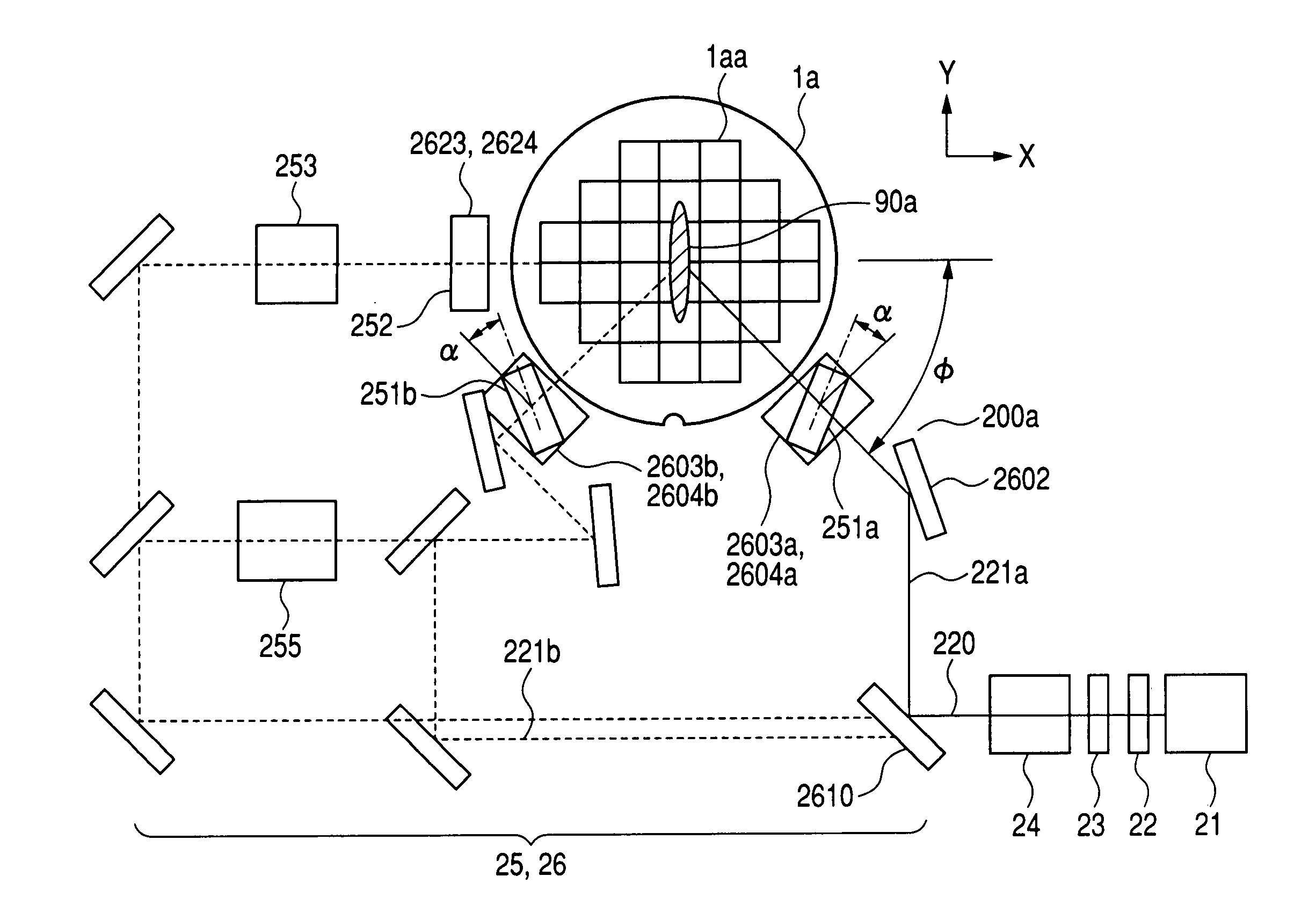
A defect inspection apparatus includes an irradiation optical system 20, a detection optical system 30, and an image processor 40. In the irradiation optical system, a mirror 2603 is disposed to reflect downward a beam flux that has been guided to a first or second optical path, and a cylindrical lens 251 and an inclined mirror 2604 are disposed to focus the beam flux that has been directed downward by the mirror, at an inclination angle from a required oblique direction extending horizontally, onto a substrate 1 to be inspected, as a slit-shaped beam 90.

Description

BACKGROUND OF THE INVENTION[0001]The present invention relates to an apparatus and method for inspecting defects, adapted to detect and analyze contamination and other defects occurring during the manufacturing processes of a desired object that include forming patterns on a substrate, to provide appropriate measures against contamination and other defects, and to inspect the occurrence status thereof. The manufacturing processes include semiconductor manufacturing processes, liquid-crystal display device manufacturing processes, printed-circuit board manufacturing processes, and the like.[0002]During conventional semiconductor-manufacturing processes, the presence of dust particles or other foreign substances (hereinafter, referred to collectively as contamination) on the surface of a semiconductor substrate (wafer) causes defects such as the improper insulation or short-circuiting of wiring. In addition, if a semiconductor device becomes fine-structured to form fine-structured con...

Claims


Application Information

Patent Timeline
Patent Type & Authority Patents(United States)
IPC IPC(8): G01N21/88
CPCG01N21/94G01N21/9501G01N21/95607G01N21/95623H01L22/12G01N2021/9513G01N2021/95638
Inventor NAKANO, HIROYUKIHAMAMATSU, AKIRAUTO, SACHIOOSHIMA, YOSHIMASANISHIYAMA, HIDETOSHIURANO, YUTAMAEDA, SHUNJI
Owner HITACHI HIGH-TECH CORP
Learn More