Magnetic recording and reproducing apparatus, method of controlling the same, magnetic recording medium, and stamper for manufacturing magnetic recording medium
a technology of magnetic recording and reproducing apparatus, which is applied in the direction of recording signal processing, maintaining head carrier alignment, instruments, etc., can solve the problems of increased limited improvement of positioning accuracy of magnetic head, and high risk of error in position control signals, etc., to reduce manufacturing burden and manufacturing cost, increase the output of position control signals, and excellent
- Summary
- Abstract
- Description
- Claims
- Application Information
AI Technical Summary
Benefits of technology
Problems solved by technology
Method used
Image
Examples
first exemplary embodiment
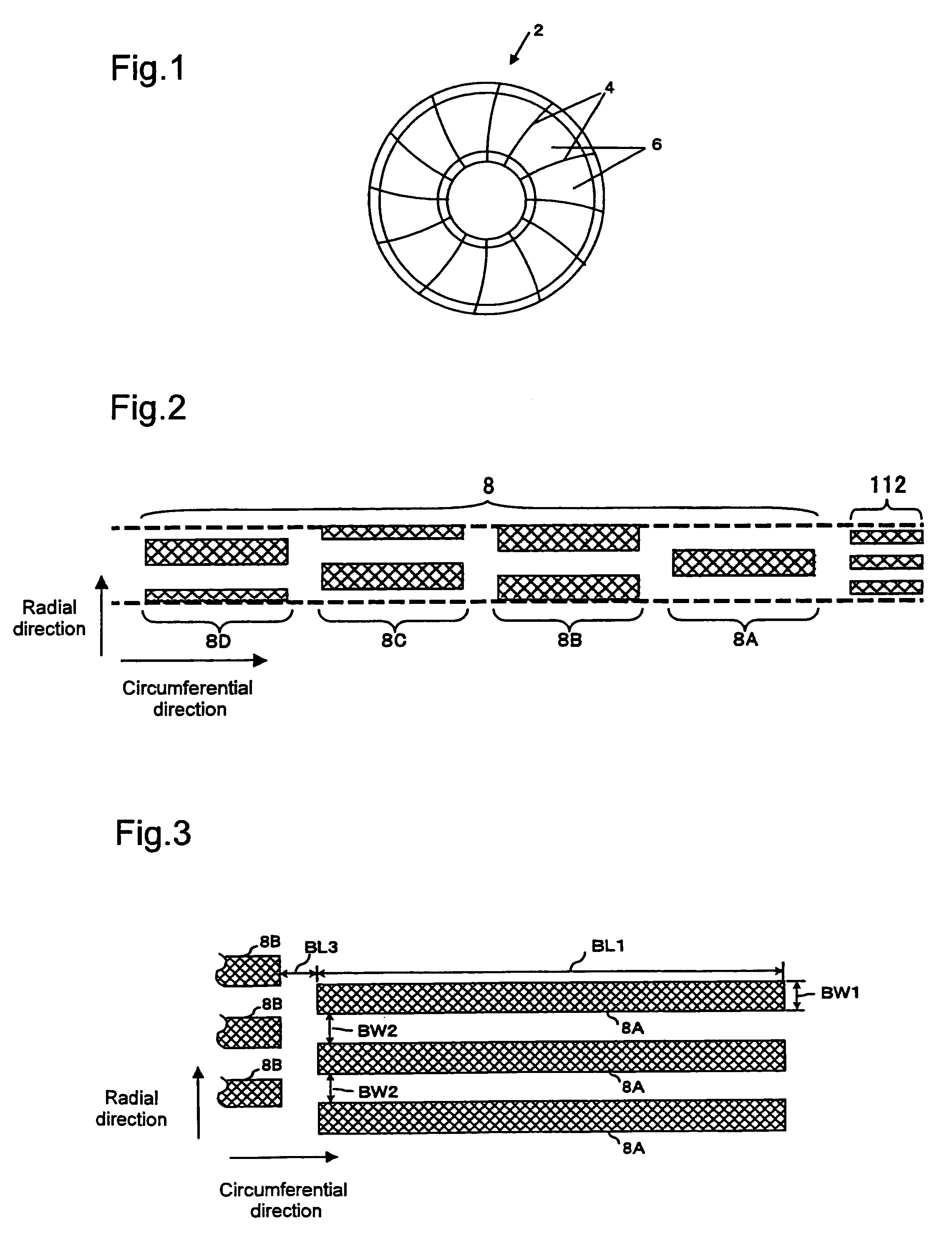
[0083]A magnetic recording and reproducing apparatus (not shown) according to the first exemplary embodiment has a magnetic recording medium 2 of disk shape as shown in FIG. 1. A plurality of servo regions 4 and user data regions 6 are formed on this magnetic recording medium 2 so that they are arranged alternately in the circumferential direction.
[0084]As enlarged in FIG. 2, each servo region 4 contains a burst pattern (positional information) which is composed of a plurality of burst signal groups 8A (8B, 8C, 8D) arranged in the radial direction. As far as the arrangement itself is concerned, the burst signal groups are the same as those of the burst pattern in the conventional magnetic recording medium 100 described above. Incidentally, the reference numeral 112 in the diagram designates data tracks for recording user data.
[0085]FIG. 3 is a diagram corresponding to FIG. 22 seen above, showing part of an enlarged burst pattern formed in a servo region 4 (the entire burst signal gr...
second exemplary embodiment
[0117]FIG. 11 is a block diagram showing a position control circuit 20 of a magnetic recording and reproducing apparatus (not shown) according to the second exemplary embodiment of the present invention.
[0118]The magnetic recording and reproducing apparatus according to the second exemplary embodiment has the position control circuit 20 instead of the position control circuit 10 in the foregoing first exemplary embodiment. The rest of the configuration is the same as in the foregoing first exemplary embodiment.
[0119]This position control circuit 20 is formed by interposing a gate circuit (a signal extractor) 22 between the amplifier 116 and the differentiator 118 of the conventional position control circuit 130 shown in FIG. 23.
[0120]The gate circuit 22 detects a servo mark which indicates the starting position of a burst pattern. With reference to this servo mark, the gate circuit 22 generates a plurality of gate pulse signals S4 for each of burst signal groups 8 such as shown in F...
third exemplary embodiment
[0135]FIG. 25 is a schematic diagram showing the plane of a single burst signal group on the magnetic recording medium of the magnetic recording and reproducing apparatus according to the third exemplary embodiment, reproduced signals corresponding to the single burst signal group, gate pulse signals, and signals generated from the reproduced signals and the gate pulse signals.
[0136]Each of single burst signal groups of the magnetic recording and reproducing apparatus according to the third exemplary embodiment consists of two convex portions and one concave portion. The rest of the configuration is the same as in the foregoing second exemplary embodiment.
[0137]In the magnetic recording and reproducing apparatus according to the third exemplary embodiment, the gate circuit 22 generates the plurality of gate pulse signals S4 for each of the reproduced signals S1 corresponding to either one of a single concave portion and a single convex portion (in the third exemplary embodiment, a s...
PUM
| Property | Measurement | Unit |
|---|---|---|
| radial width | aaaaa | aaaaa |
| radial width | aaaaa | aaaaa |
| circumferential length | aaaaa | aaaaa |
Abstract
Description
Claims
Application Information
 - R&D
- Intellectual Property
- Life Sciences
- Materials
- Tech Scout
- Unparalleled Data Quality
- Higher Quality Content
- 60% Fewer Hallucinations
Browse by: Latest US Patents, China's latest patents, Technical Efficacy Thesaurus, Application Domain, Technology Topic, Popular Technical Reports.
© 2025 PatSnap. All rights reserved.Legal|Privacy policy|Modern Slavery Act Transparency Statement|Sitemap|About US| Contact US: help@patsnap.com


