Method and system for imaging using multiple offset X-ray emission points

a technology of offset x-ray and emission point, applied in the field of non-invasive imaging, can solve the problems of large detectors, inability to produce large detectors, large detectors and associated acquisition electronics, etc., and achieve the effect of small in-plane exten

Active Publication Date: 2008-02-19
GENERAL ELECTRIC CO
View PDF81 Cites 94 Cited by
  • Summary
  • Abstract
  • Description
  • Claims
  • Application Information

AI Technical Summary

Problems solved by technology

Larger detectors, however, may be undesirable for a variety of reasons.
For instance, as one might expect, larger detectors and associated acquisition electronics are both more costly and more difficult to produce.
In addition, the mechanical subsystem responsible for supporting and / or rotating a larger detector may also need to be larger and more complex and / or may be subject to greater mechanical stress.
The increased cone angle between the source and detector periphery is in turn associated with increased cone-beam artifacts in the reconstructed images.
When the cone angle increases beyond a certain limit, the degradation of the image quality may become severe for axial, or step and shoot scanning.
For this reason, it may be difficult to increase the scan coverage by simply increasing the coverage, i.e., size of the detector.

Method used


Image

  • Method and system for imaging using multiple offset X-ray emission points
  • Method and system for imaging using multiple offset X-ray emission points
  • Method and system for imaging using multiple offset X-ray emission points

Examples


Embodiment Construction

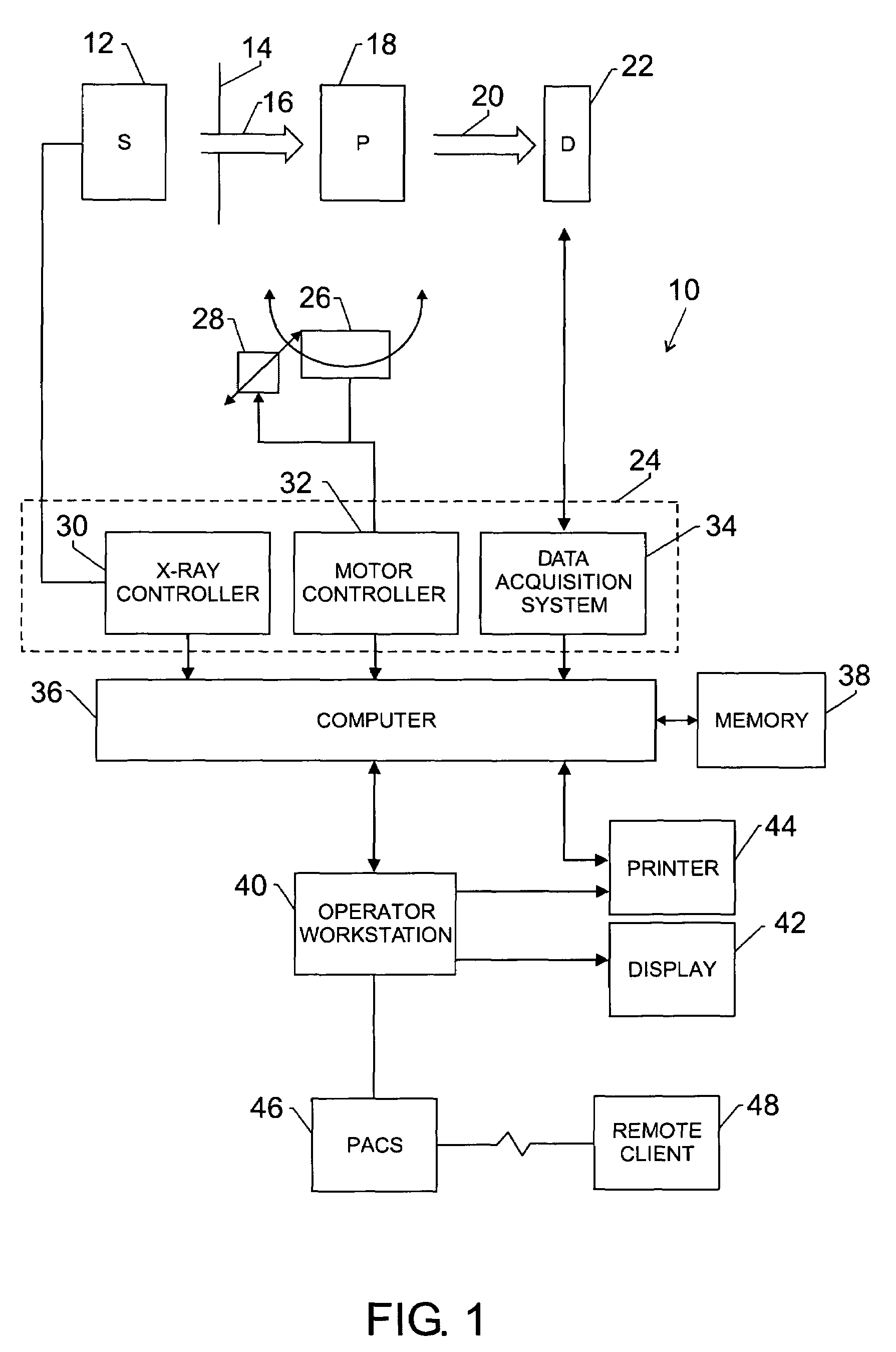
[0018]FIG. 1 illustrates diagrammatically an imaging system 10 for acquiring and processing image data. In the illustrated embodiment, system 10 is a computed tomography (CT) system designed to acquire X-ray projection data, to reconstruct the projection data into an image, and to process the image data for display and analysis in accordance with the present technique. Though the imaging system 10 is discussed in the context of medical imaging, the techniques and configurations discussed herein are applicable in other non-invasive CT imaging contexts, such as baggage or package screening.

[0019]In the embodiment illustrated in FIG. 1, CT imaging system 10 includes a source 12 of X-ray radiation. As discussed in detail herein, the source 12 of X-ray radiation may consist of two or more discrete, i.e., separated, emission points. For example, a conventional X-ray tube may be equated with a single emission point. Alternatively, an X-ray source such as a solid-state X-ray source having f...


PUM

PropertyMeasurementUnit
radiusaaaaaaaaaa
radiusaaaaaaaaaa
CT imagingaaaaaaaaaa

Abstract

A technique is provided for imaging a field of view using an X-ray source comprising two or more emission points. Each emission point is configured to emit a fan of radiation encompassing less than the entire field of view. The emission points are activated individually and rotate about the field of view, allowing respective streams of radiation to be emitted at various view angles about the field of view. The emission points, which may correspond to different radial regions of the field of view, may be differentially activated to emphasize a region of interest within the field of view. The multiple emission points may be extrapolated along the longitudinal axis in duplicate or offset configurations.

Description

BACKGROUND OF THE INVENTION[0001]The present invention relates generally to the field of non-invasive imaging and more specifically to the field of computed tomography (CT) imaging. In particular, the present invention relates to source configurations useful in CT imaging.[0002]CT scanners operate by projecting fan-shaped or cone-shaped X-ray beams from an X-ray source. The X-ray source emits X-rays at numerous view angle positions about an object being imaged, such as a patient, which attenuates the X-ray beams as they pass through. The attenuated beams are detected by a set of detector elements, which produce signals representing the intensity of the incident X-ray beams. The signals are processed to produce data representing the line integrals of the attenuation coefficients of the object along the X-ray paths. These signals are typically called “projection data” or just “projections”. By using reconstruction techniques, such as filtered backprojection, useful images may be formu...

Claims


Application Information

Patent Timeline
Patent Type & Authority Patents(United States)
IPC IPC(8): G01N23/00A61B6/03A61B6/00G01N23/06G21K1/12H05G1/10H05G1/60
CPCA61B6/032A61B6/4028A61B6/4085A61B6/027
Inventor DE MAN, BRUNOEDIC, PETER MICHAELBASU, SAMIT
Owner GENERAL ELECTRIC CO
Why Eureka
Try Eureka