Fixing device with temperature control

a fixing device and temperature control technology, applied in the field of fixing devices, can solve the problems of significant increase in power consumption of the fixing device or the entire image forming apparatus including the fixing device, and the time needed before the fixing roller is heated to a temperature at which fixing is possible, and achieve the effect of quick heating and easy mounting

Inactive Publication Date: 2008-02-19
RICOH KK
View PDF32 Cites 31 Cited by
  • Summary
  • Abstract
  • Description
  • Claims
  • Application Information

AI Technical Summary

Benefits of technology

[0015]Because of these reasons, the present inventors recognized a need exists for a fixing device which is space effective, cost effective, easy to mount, which can be quickly warmed up and by which a temperature rise in the fixing member included in the fixing device during a fixing process can be effectively prevented.
[0016]Accordingly, an object of the present invention is to provide a novel fixing device which is space effective, cost effective, easy to mount, quickly warms up, and by which a temperature rise in the fixing member included in the fixing device during a fixing process can be effectively prevented. A further object is to provide a novel image forming apparatus using the fixing device.

Problems solved by technology

However, since this thermal roller fixing system uses a fixing roller having a large thermal capacity, the time needed before the fixing roller is heated to a temperature at which fixing is possible is relatively long.
Therefore, the warm-up time of the device is inevitably set to be long in most cases.
Further, a large amount of power is needed to maintain the temperature of such a fixing roller, resulting in significant increase in power consumption of the fixing device or the entire image forming apparatus including the fixing device.
However, when a large number of small sized recording materials are continuously printed with a fixing device using a fixing member having such a low thermal capacity, the end portion of the fixing member in which materials do not pass is heated to a high temperature, which may lead to a life length problem of the fixing member.
As a result, there may be a difference in the gloss obtained between the central portion and the end portion of the recording material.
Further, since the temperature at the area outside a small-sized recording material rises while a large number of the small-sized recording materials continuously pass, hot-offset and wound material jamming possibly occur to a large-sized material printed immediately thereafter.
However, to wind an exciting coil around a magnetic core, which is illustrated in JOP H12-206813, is laborious.
Therefore, such a magnetic field generating device has a poor assembling property.
Also such a magnetic field generating device is costly.
Therefore, when a plurality of such magnetic field generating devices are provided to prevent the temperature of the end portion of a recording material from rising, costs become extremely high.
The technique described in JOP H12-206813 requires a plurality of magnetic field generating devices, resulting in significantly poor mountability and increase in costs.
Further, since the amount of power supplied to the heating coils located at the ends is controlled depending on the amount of power supplied to the heating coil in the center, the control circuit is complicated, resulting in further increases in cost.
Furthermore, since the coil is divided, the temperature is not uniform at the connecting points of the coils, thereby creating non-uniform gloss.
Similarly, in the technique of JOP 2001-117401, a plurality of magnetic field generating mechanisms are provided and therefore its cost is extremely high.
In addition, even though the magnetic field generating mechanisms are space-consuming, the magnetic field generating mechanisms are arranged in two lines, resulting in increase in size.
Therefore, as compared with electromagnetic induction heat generation, heat generation efficiency is inferior and warm-up time is long.
In the technique of JOP H08-220932, since a halogen heater is the only heat source, the heat generation efficiency is inferior to that of a device using electromagnetic induction heat generation and the warm-up time is relatively long.

Method used


Image

  • Fixing device with temperature control
  • Fixing device with temperature control
  • Fixing device with temperature control

Examples


Embodiment Construction

[0035]The present invention will be described below in detail with reference to several embodiments and accompanying drawings.

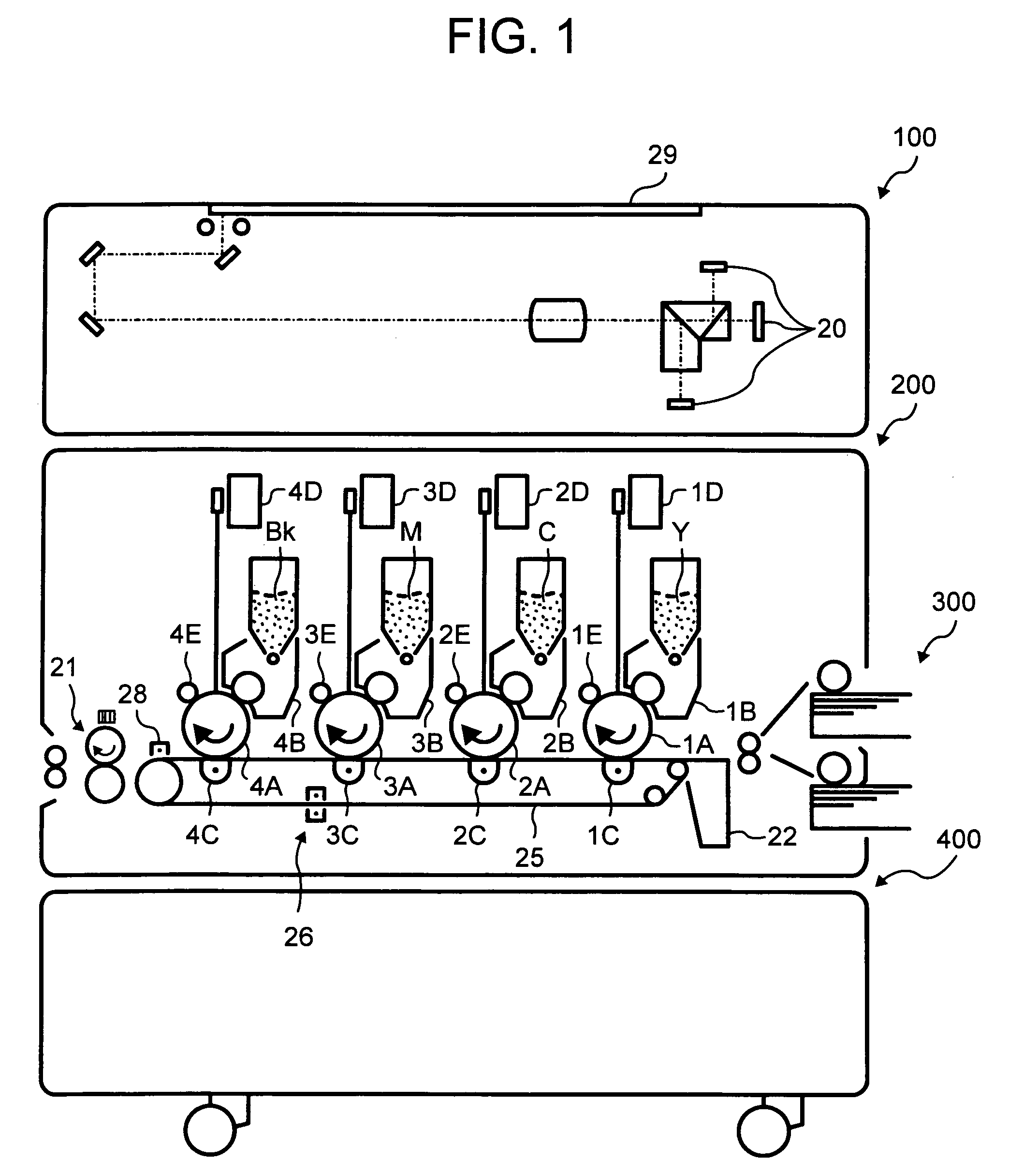
[0036]First, the structure of an example of a color image forming apparatus to which the present invention is applied is now described with reference to FIG. 1. The color image forming apparatus described here includes an image reading unit 100, an image forming portion 200, a manual material feeding device 300 and a material feeder portion. The image forming portion 200 has a fixing device 21 and a plurality of photoreceptors 1A, 2A, 3A and 4A arranged in a row. These photoreceptors 1A to 4A rotate in the direction indicated by the arrow in FIG. 1 and are formed of organic or inorganic materials having photoconductivity.

[0037]Color separation overlapping transfer systems are typically used for a full-color image forming apparatus based on electrophotography. Such an image forming apparatus operates as follows:[0038](1) Each document reading portion reads ima...


PUM


Abstract

A fixing device including a magnetic field generating device to generate a magnetic field, a fixing member to heat a recording material by heat generated in a first recording material passing area having a first width on the fixing member by electromagnetic induction heat generation by the magnetic field formed by the magnetic field generating device, a pressing member to form a nip portion where the pressing member and the fixing member press against each other to fix an unfixed image on the recording material, and at least one radiation heating device configured to heat a second recording material passing area having a second width.

Description

BACKGROUND OF THE INVENTION[0001]1. Field of the Invention[0002]The present invention relates to a fixing device for use in an image forming apparatus adopting an electrophotographic system, and particularly relates to a fixing device in which the temperature is prevented from rising at its end portions.[0003]2. Discussion of the Background[0004]A typical fixing system for use in electrophotography is a thermal roller fixing system including a fixing roller containing a heat source therein and a pressing roller covered with an elastic body. The surface of the fixing roller is also covered with a non-adhesive elastic body. In this system, a toner borne on a recording material is fixed upon application of heat and pressure when a recording material passes between both rollers. However, since this thermal roller fixing system uses a fixing roller having a large thermal capacity, the time needed before the fixing roller is heated to a temperature at which fixing is possible is relativel...

Claims


Application Information

Patent Timeline
Patent Type & Authority Patents(United States)
IPC IPC(8): G03G15/16G03G15/20
CPCG03G15/2042G03G2215/2016G03G2215/2032G03G2215/2035G03G2215/1695G03G2215/2006
Inventor BABA, TOSHIHIKOKUROTAKA, SHIGEOECHIGO, KATSUHIROFUJITA, TAKASHIKIKUCHI, HISASHISOMEYA, YUKIMICHIKUNII, HIROYUKINAKAFUJI, ATSUSHIUE, KOHJI
Owner RICOH KK
Why Eureka
Try Eureka