
Performance monitor for a photovoltaic supply

a technology of photovoltaic supply and performance monitor, which is applied in the direction of optical radiation measurement, instruments, nuclear elements, etc., can solve the problems of reducing output, blocking sunlight, and accumulating dirt and dus

Inactive Publication Date: 2008-02-19
BP CORP NORTH AMERICA INC
View PDF2 Cites 44 Cited by
  • Summary
  • Abstract
  • Description
  • Claims
  • Application Information

AI Technical Summary

Benefits of technology

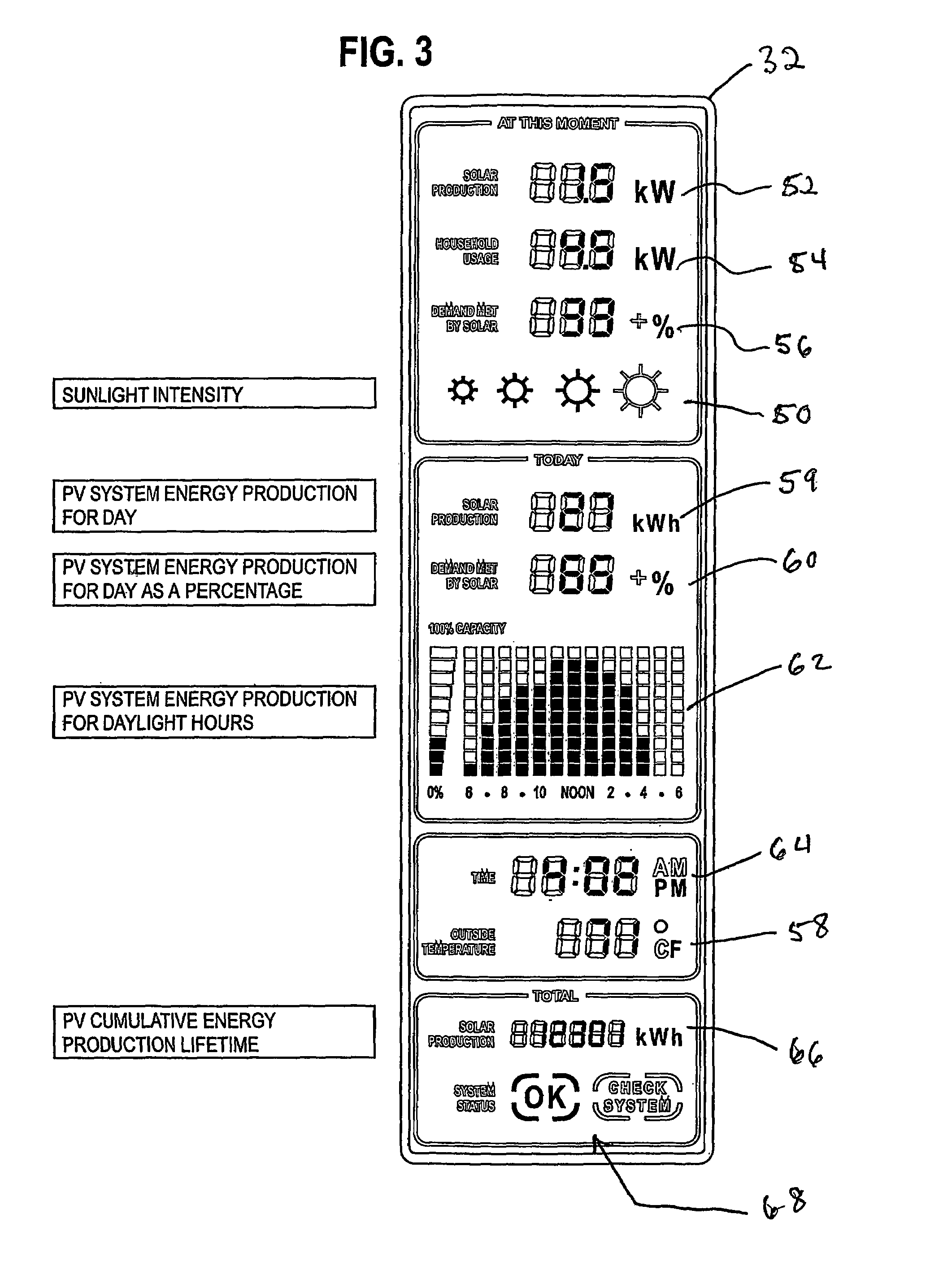
The present invention is a method and apparatus for monitoring the performance of a solar powered electrical supply for an electrical load. The apparatus includes an irradiance sensor, a circuit for deriving a running performance signal, a radio for broadcasting the performance signal, and a portable unit for receiving the performance signal and displaying it visually. The portable unit includes indicators such as solar irradiance, temperature, time, photovoltaic power production, and other performance indicators. The invention allows owners of solar power systems to understand what is happening and how their system is performing. It also provides an improved and efficient method and apparatus for monitoring solar power system performance.

Problems solved by technology

Dirt and dust can accumulate on the solar module surface, blocking some of the sunlight and reducing output.
Mismatch and Wiring Losses
This difference is a result of slight inconsistencies in performance from one module to the next, and is called “module mismatch” and can amount to at least a 2% loss in system power.
Power is also lost to resistance in the system wiring.
These losses should be kept to a minimum but it is often difficult to keep these losses below 3% for the system.
Some power is lost in the conversion process, and there are additional losses in the wires from the rooftop array down to the inverter and out to the house panel.
A deviation of the tilt angle of 30 degrees from the optimum angle, will lead to less than 10% loss of the maximum yield.
If the owner suddenly begins using more electricity, they may not see much decrease in their bill and assume the PV system is under-performing.
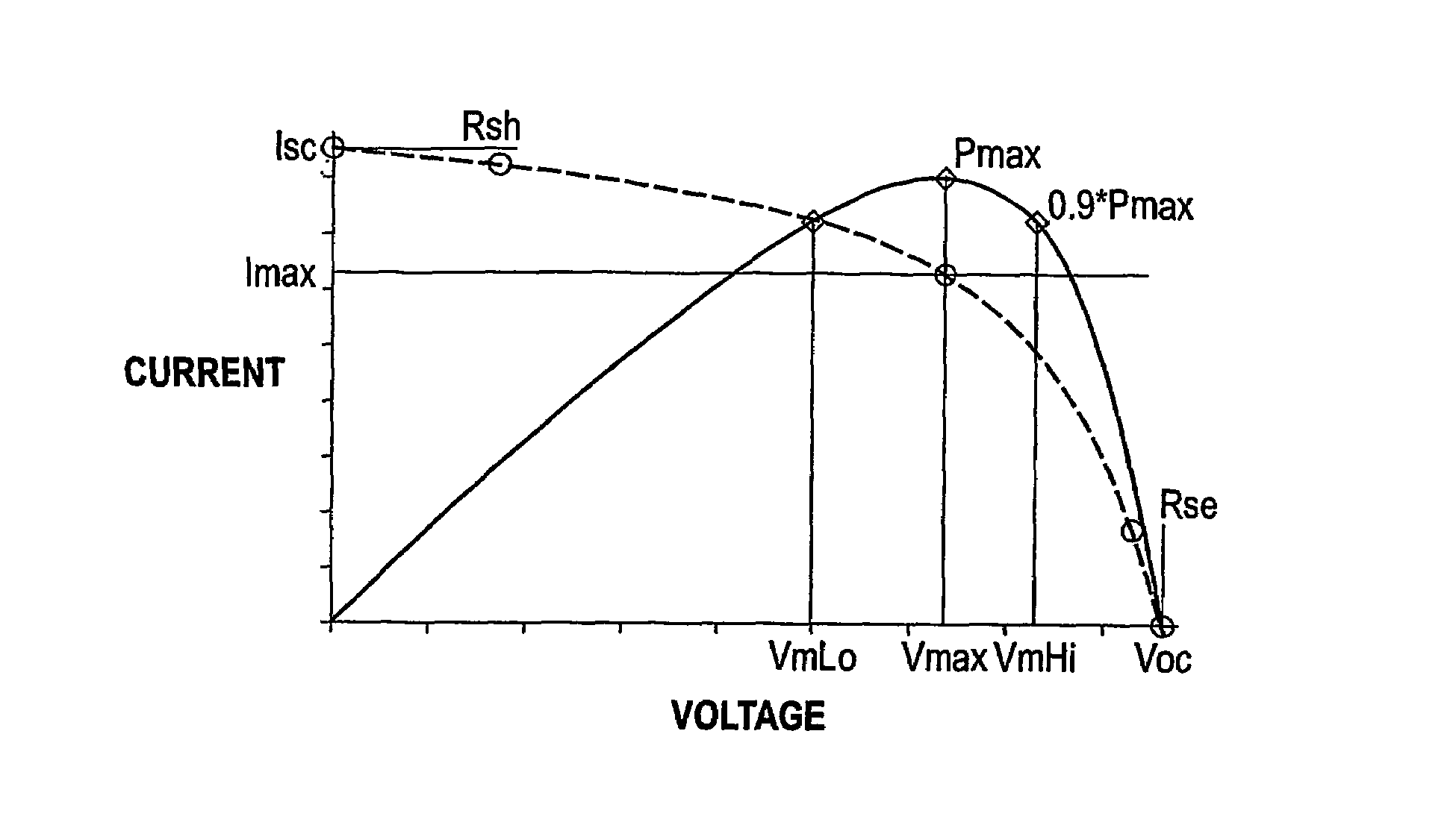
However, when PV arrays are installed and used: during low light level periods (e.g. winter time), or during extreme temperatures, or during high solar incidence angles, then it is difficult to correct back to STC for the modules, as errors are largest when the biggest corrections in temperature and irradiance are made.
It also has been difficult to check if the array was set up and performing as expected.
This problem has existed for some time.
Considerable effort has been made, and significant amounts of money have been expended, to resolve this problem.
In spite of this, the problem still exists.
Actually, the problem has become aggravated with the passage of time because solar power systems are becoming more common and are being owned by consumers who do not know subtle solar engineering design factors.

Method used


Image

  • Performance monitor for a photovoltaic supply
  • Performance monitor for a photovoltaic supply
  • Performance monitor for a photovoltaic supply

Examples


Embodiment Construction

[0034]While this invention is susceptible of embodiment in many different forms, there is shown in the drawings, and will herein be described in detail, several specific embodiments of the invention. It should be understood, however, that the present disclosure is to be considered an exemplification of the principles of the invention and is not intended to limit the invention to any specific embodiment so described.

[0035]Before describing the invention in detail, the environment of the invention will be explained.

Typical System Components

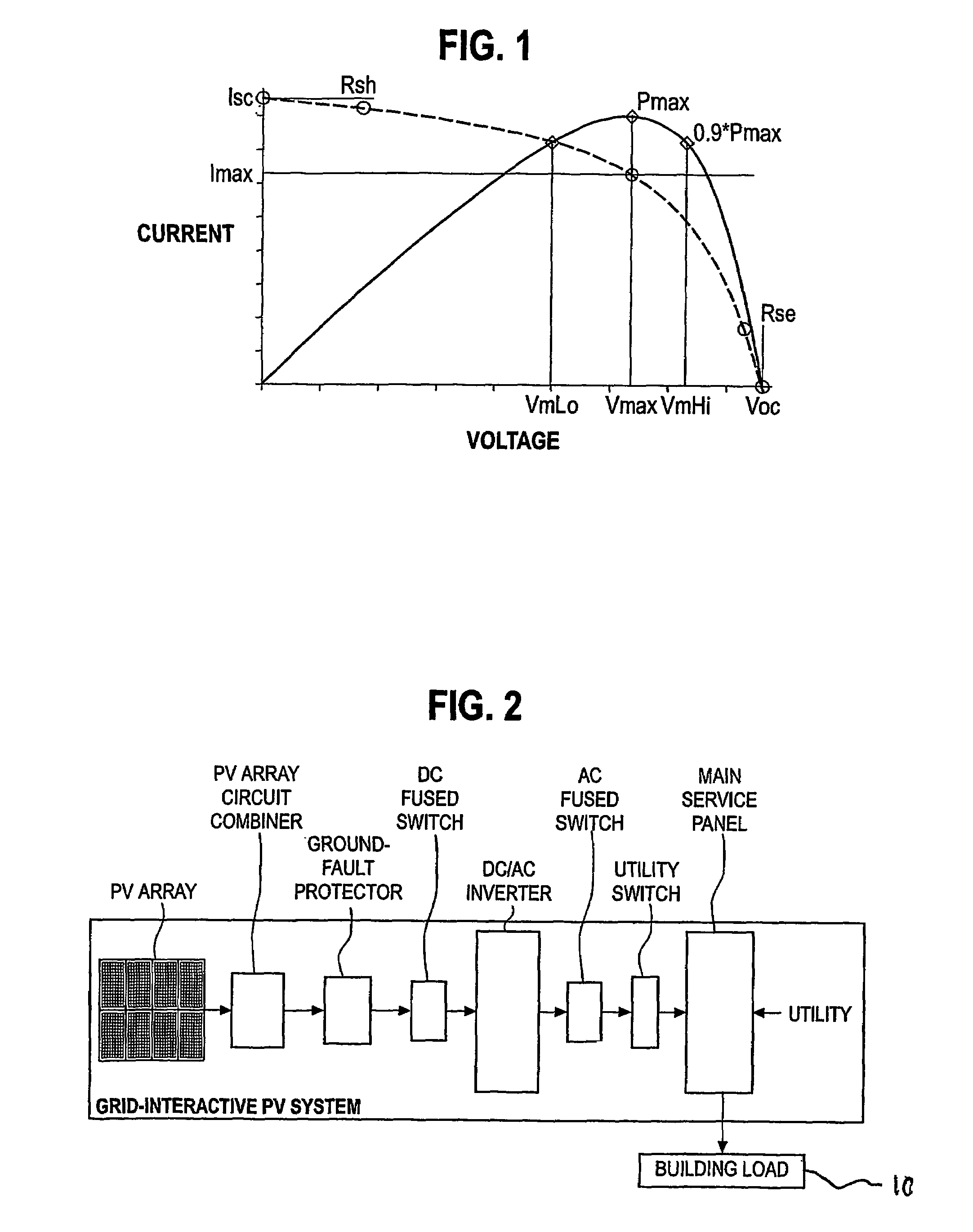
[0036]A typical solar electrical power system (see FIG. 2) comprises: a PV Array, Balance of System Equipment, a DC to AC Inverter, and other components.

[0037]PV Array: Common PV modules are 5 to 25 square feet in size and weigh about 3 to 4 lbs. / ft2. Often sets of four or more smaller modules are framed or attached together by struts in what is called a panel. This panel is typically around 20 to 35 square feet in area for ease of handling on a roo...


PUM


Abstract

A method and apparatus is disclosed for monitoring the performance of a solar powered electrical supply where the supply comprises an array of photovoltaic cells that are mounted on a building. In one embodiment, the apparatus comprises: a device for producing a signal representative of solar irradiance; circuitry for computing a running performance signal by using at least the irradiance signal and a measure of the electrical power supplied to the load from the array; a radio for broadcasting the performance signal; and a portable unit for receiving the performance signal from the radio and for visually displaying the performance signal, power production, and electrical utility usage.

Description

CROSS-REFERENCE TO RELATED APPLICATIONS[0001]This is a Patent Application claiming the priority of a USA Provisional Patent Application filed on Apr. 4, 2003 under Ser. No. 60 / 460,502 and entitled “PV Performance Monitor.”STATEMENT REGARDING FEDERALLY—SPONSORED RESEARCH OR DEVELOPMENT[0002]Not applicableREFERENCE TO A “MICROFICHE APPENDIX[0003]Not applicableTECHNICAL FIELD[0004]This invention relates to the general subject of methods and apparatus for converting sunlight into electricity, and, in particular, to methods and apparatus used to display the performance of a photovoltaic power supply.BACKGROUND OF THE INVENTION[0005]The photovoltaic (PV) module is the basic building block of PV electrical systems. A PV module is composed of interconnected cells that are encapsulated between a glass cover and weatherproof backing. The modules are typically framed in aluminum frames suitable for mounting. The term “solar panel” is often used to refer to a PV module. However, the same expres...

Claims


Application Information

Patent Timeline
Patent Type & Authority Patents(United States)
IPC IPC(8): G06F15/00G01R31/26
CPCH02S50/10Y02B10/10Y02E10/50G01J1/4204G01R11/32G01R22/06G08B5/22G08B21/182H01L31/101
Inventor WARFIELD, DONALD B.GARVISON, PAUL
Owner BP CORP NORTH AMERICA INC
Learn More