Suction brush assembly and a vacuum cleaner having the same

a vacuum cleaner and assembly technology, applied in the direction of vacuum cleaners, domestic applications, exhaust air diffusion, etc., can solve the problems of affecting the cleaning efficiency of the cleaning member, and the loss of the effectiveness of the cleaning member's rotation body 80, so as to improve the cleaning efficiency and reduce the noise of the high frequency region , the effect of smooth rotation

Active Publication Date: 2008-02-26
SAMSUNG GWANGJU ELECTRONICS CO LTD
View PDF17 Cites 17 Cited by
  • Summary
  • Abstract
  • Description
  • Claims
  • Application Information

AI Technical Summary

Benefits of technology

[0011]There is provided, a suction brush assembly capable of preventing dust from accumulating in areas where, over time, it can impede the operation of rotating cleaning members, thereby improving a cleaning efficiency, and a vacuum cleaner having the same. The suction brush assembly also produces less noise than do prior art suction brush assemblies.
[0013]The suction brush assembly in another embodiment also comprises an assembly body having a suction inlet for drawing in dust from a surface being cleaned; a cover connected to the assembly body; a turbine fan rotatably mounted to the assembly body; a suction path for guiding an air drawn in through the suction inlet to the turbine fan; and a path partition defining the suction path and having a plurality of holes. Inflow of the dust through a gap between the rotation body and the assembly body can be prevented to improve an efficiency of the cleaning work. Further, noise of high frequency, generated form the turbine fan and other component parts can be reduced.
[0015]The external air, drawn in through the first and the second openings as described above, is passed through a gap formed between the rotation body and the rotation body mounting boss of the assembly body and discharged out to a lower part of the assembly body. Therefore, the dust can be prevented from flowing to the rotation body through the gap, and accordingly, the rotation body can smoothly rotated, thereby improving the cleaning efficiency.
[0016]In addition, noise generated from the turbine fan and other component parts, especially, the noise of a high frequency region, can be reduced since the noise is absorbed into the sound-absorbing member through the holes while being discharged to the suction inlet through the suction path.

Problems solved by technology

Over time, the cleaning member's rotation body 80 loses its effectiveness and cleaning effectiveness deteriorates.
The noise, especially of high frequency region, may be offensive to a user.

Method used


Image

  • Suction brush assembly and a vacuum cleaner having the same
  • Suction brush assembly and a vacuum cleaner having the same
  • Suction brush assembly and a vacuum cleaner having the same

Examples


Embodiment Construction

[0027]Hereinafter, an embodiment of the present invention will be described in detail with reference to the accompanying figures. In the following description, drawing reference numerals are used for the same elements in different drawings. The embodiments described herein are only examples and are not intended to limiting the invention disclosed herein. Rather, the invention disclosed herein is defined by set forth in the appurtenant claims. Also, well-known functions and structures are not described in detail, since they would tend to obscure the claimed invention in unnecessary detail.

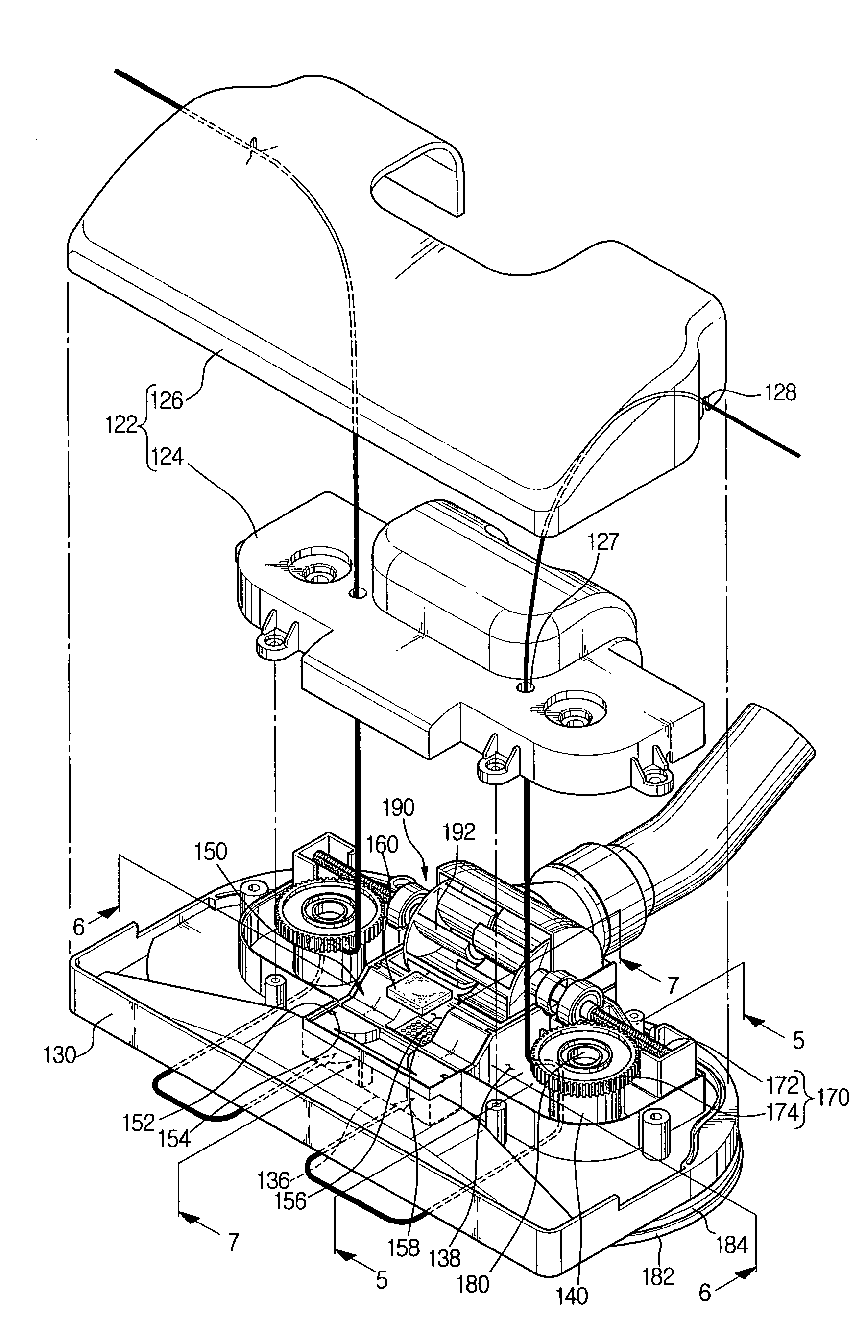
[0028]Referring to FIG. 4, a preferred embodiment of a suction brush assembly comprises a two-piece cover 122, a lower assembly body 130 connected to the cover 122 and having a suction inlet 136 at a bottom surface thereof. A turbine fan 190 is rotatably mounted to the assembly body 130. A suction path-forming member 150 is disposed in front of the turbine fan 90 and mounted on the assembly body 130...


PUM


Abstract

A suction brush assembly comprises an assembly body having a suction inlet for drawing in dust on a surface being cleaned, a cover connected to the assembly body and having an opening for drawing in an external air, and a rotation body rotatably mounted to the assembly body and mounting a detachable cleaning member at a lower part thereof for contact with the surface being cleaned. The external air drawn in through the opening flows out to a lower part of the assembly body through a gap formed between the rotation body and the assembly body. Accordingly, the dust can be prevented from flowing into the rotation body, thereby improving an efficiency of a cleaning work.

Description

CROSS-REFERENCE TO RELATED APPLICATIONS[0001]This application claims the benefit of Korean Patent Application Nos. 2004-57754 and 2004-25183, filed Jul. 23, 2004, in the Korean Intellectual Property Office, the disclosure of which is incorporated herein by reference.FIELD OF THE INVENTION[0002]The present invention relates to a suction brush for a vacuum cleaner. More particularly, the present invention relates to a suction brush providing an more-efficient cleaning and reduced noise as well as a vacuum cleaner having the same.BACKGROUND OF THE INVENTION[0003]FIG. 1 is an exploded perspective view showing a prior art vacuum cleaner. The vacuum cleaner comprises a cleaner body 1 that encloses therein, a motor for driving a fan that generates a suction force. The vacuum cleaner also includes an extension hose 10 connected to the cleaner body 1, and a suction brush assembly 20 connected to the extension hose 10 through which dust on a surface being cleaned is drawn.[0004]The extension ...

Claims


Application Information

Patent Timeline
Patent Type & Authority Patents(United States)
IPC IPC(8): A47L9/04A47L9/00A47L9/02A47L9/06
CPCA47L9/0081A47L9/0416A47L9/02A47L9/04
Inventor SONG, HWA-GYUKIM, HOA-JOONG
Owner SAMSUNG GWANGJU ELECTRONICS CO LTD
Why Eureka
Try Eureka