Torque limiting driver and assembly

a technology of torque limiter and torque limiter, which is applied in the direction of screwdrivers, power driven tools, wrenches, etc., can solve the problems of time-consuming, ineffective driven objects, and diminishing the usefulness of drivers, so as to achieve accurate calibration, efficient and easy, and efficient drivers

Active Publication Date: 2008-02-26
BRADSHAW MEDICAL
View PDF25 Cites 85 Cited by
  • Summary
  • Abstract
  • Description
  • Claims
  • Application Information

AI Technical Summary

Benefits of technology

[0006]When the drive assembly is inserted into the housing, the locking screw is located near the closed end of the housing, which gives added support and stability for the locking screw compared to prior art arrangements.
[0007]The present invention also encompasses a method for making the above driver. A testing assembly is provided that will receive the drive assembly of the driver, with all of the various components of the drive assembly secured on the drive shaft. Once inserted into the testing assembly, the drive assembly can be properly and accurately calibrated. The drive assembly will be inserted into the housing and secured to the housing. The method allows for a more efficient and easy way of calibrating the drive mechanics compared to the prior art, which results in a more efficient driver.

Problems solved by technology

Even though there is a large amount of torque being delivered, in many situations, it is still desirous to control the precise amount of torque being delivered.
For instance, too much torque may strip the object that is being driven, which would lead to the driven object becoming ineffective, such as a stripped bolt or screw.
If the parts are not assembled properly, the arrangement of the driver may not deliver a proper amount of torque, which diminishes the usefulness of the driver.
This can be time consuming, specifically when assembling a large number of tools at one time.

Method used


Image

  • Torque limiting driver and assembly
  • Torque limiting driver and assembly
  • Torque limiting driver and assembly

Examples


Embodiment Construction

[0022]Although the disclosure hereof is detailed and exact to enable those skilled in the art to practice the invention, the physical embodiments herein disclosed merely exemplify the invention which may be embodied in other specific structures. While the preferred embodiment has been described, the details may be changed without departing from the invention, which is defined by the claims.

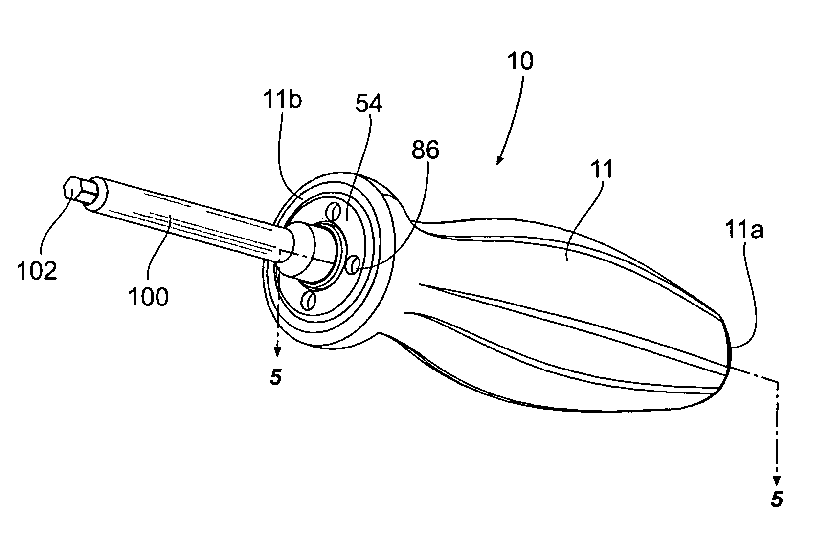
[0023]FIG. 1 is a perspective view of a torque-limiting driver 10 assembled according to the present invention. The driver 10 comprises a handle 11 having a first end 11a and a second end 11b. The handle 11 is coupled to a tool 100 at the second end 11b, with the tool 100 having an area 102 for engaging a device for which the driver 10 will provide torque or driving force. The area 102 is shown to be a hex wrench, but could be a screwdriver, wrench, or any other tool arrangement. A threaded locking screw 54 secures the tool 100 to the handle 11.

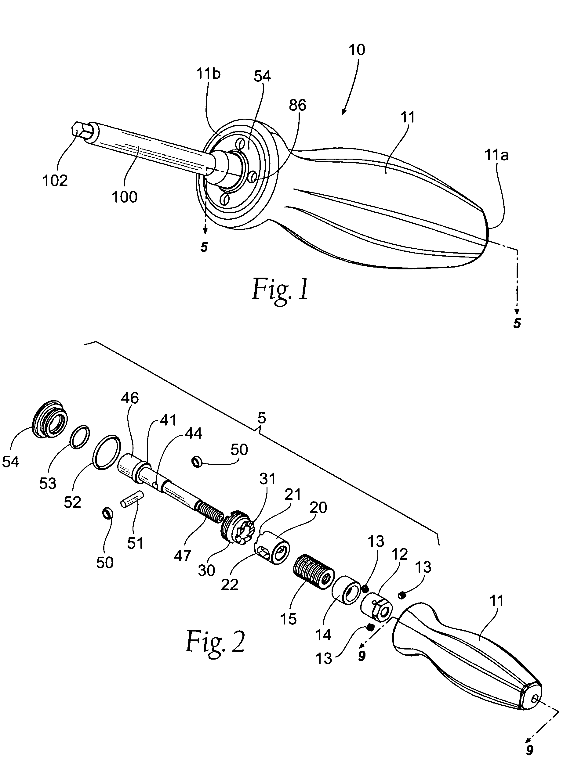
[0024]FIG. 2 provides an exploded view of the handle ...


PUM


Abstract

A method for assembling a torque-limiting driver, and the resulting drive. The method comprises the steps of providing a handle having a housing, drive assembly, and a testing assembly. The drive assembly is assembled, inserted into the testing assembly and calibrated. The drive assembly is then removed and inserted into the housing of the handle and secured to the handle.

Description

BACKGROUND OF THE INVENTION[0001]The present invention relates to mechanical drive devices for tools and the like, and, more specifically, to drive devices that will limit the torque being delivered by the device to an attached tool member.[0002]Many mechanical devices are used to deliver a large amount of torque to a screw, bolt, nut, or other similar device or object. Even though there is a large amount of torque being delivered, in many situations, it is still desirous to control the precise amount of torque being delivered. For instance, too much torque may strip the object that is being driven, which would lead to the driven object becoming ineffective, such as a stripped bolt or screw. This is especially important in medical operations and procedures, where precision is critical, such as when working with spinal and skeletal structures and related devices. Thus, drivers have been developed to limit the amount of torque delivered to the driven object or device.[0003]Because the...

Claims


Application Information

Patent Timeline
Patent Type & Authority Patents(United States)
IPC IPC(8): B25B23/157
CPCB25B15/02B25B23/141B25B23/1427
Inventor GAO, HUA
Owner BRADSHAW MEDICAL
Why Eureka
Try Eureka