
Engine configuration for a motorcycle

a technology for engine configuration and motorcycles, applied in the direction of machines/engines, cycles, auxiliaries, etc., can solve the problems of reducing the volume of lubricating oil, reducing engine performance, and affecting the performance of the engine, so as to reduce the distance between the crank chamber and the lubricant oil chamber, reduce the agitation of lubricating oil, and reduce the lubricating oil volum

Active Publication Date: 2008-02-26
HONDA MOTOR CO LTD
View PDF11 Cites 35 Cited by
  • Summary
  • Abstract
  • Description
  • Claims
  • Application Information

AI Technical Summary

Benefits of technology

[0016]In order to achieve the second object of the invention, a motorcycle is constructed by providing a seat and a storage box that are vertically stacked on each other in a rear portion of a body frame. The motorcycle also includes a pivotally mounted powertrain unit suspended from the body frame under the storage box. In this motorcycle, a fourth aspect of the invention is directed to a lubrication-oil passage structure for an engine disposed between each of a pair of journal bearing portions which are formed in a crankcase. The crankcase has an enclosed crank chamber, and a crankshaft which is freely rotatably supported by the journal bearing portions with plain bearings. The pair of journal bearing portions is provided with lubrication-oil entrance barriers for preventing lubricating oil from entering the crank chamber from outside of the crankcase.
[0025]According to the sixth aspect of the invention, in addition to the fourth or fifth aspect of the invention, the communicating oil passages provided to the journal bearing portion assist in the prevention of entrance of the lubricating oil into the crankcase, and machining of the passages is easy.

Problems solved by technology

As a result, it becomes difficult for a passenger to get on and off the motorcycle.
Further, when it is attempted to restrict the agitation resistance, it is necessary to reduce a volume of the lubricating oil.
In any case, a decrease of engine performance occurs.

Method used


Image

  • Engine configuration for a motorcycle
  • Engine configuration for a motorcycle
  • Engine configuration for a motorcycle

Examples


Embodiment Construction

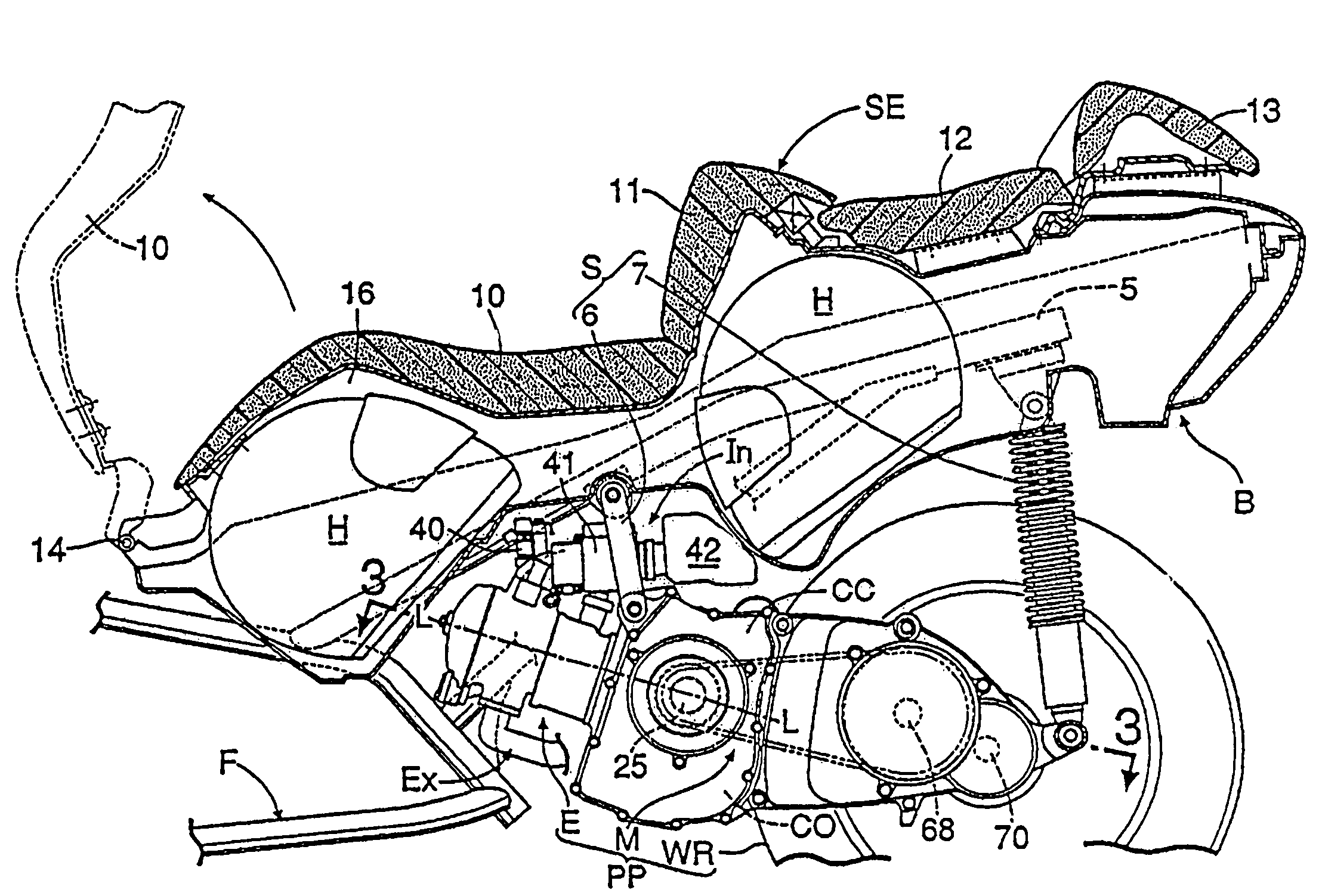
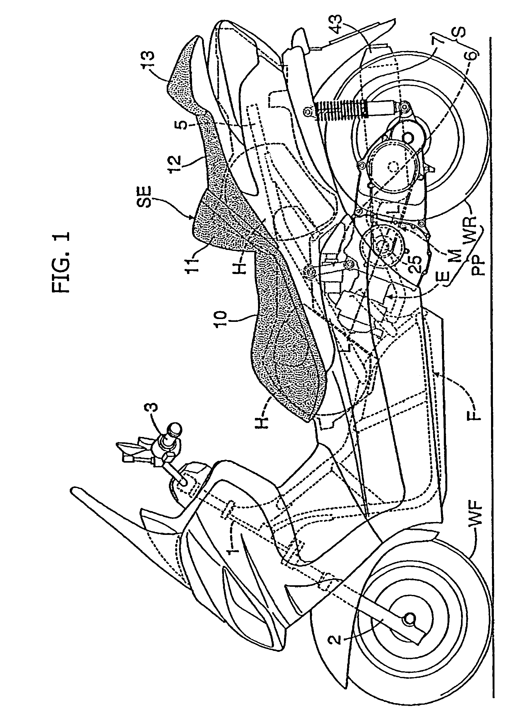
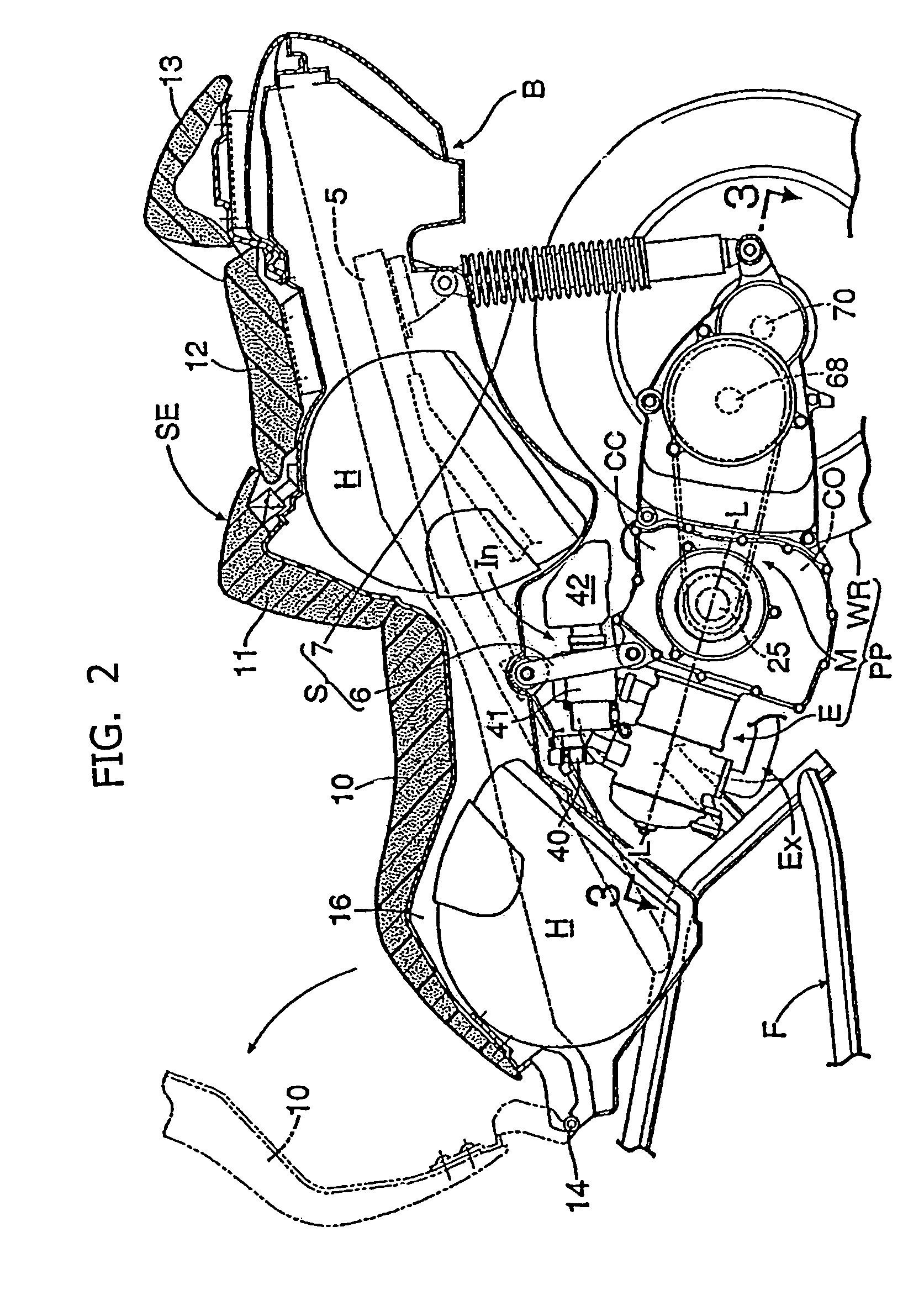
[0039]In describing the preferred embodiment of the present invention, reference will be made herein to FIGS. 1 to 11 of the drawings in which like numerals refer to like features of the invention. Features of the invention are not necessarily shown to scale in the drawings. Note that, in the following description, relative positional terms such as “front”, “rear”, “left” and “right” are described from the vantage point of a driver seated on the motorcycle and facing forward.

[0040]Referring now to FIGS. 1 to 11, embodiments of a motorcycle in accordance with the present invention will be explained below. The embodiments of the present invention include not only a motorcycle, but also a lubrication-oil passage structure implemented in an engine for a motorcycle.

[0041]In FIGS. 1 and 2, in a scooter-type motorcycle, a front fork 2 for pivotally supporting a front wheel WF is steerably supported on a head pipe 1 at a front end of a body frame F of the motorcycle, and a steering handleba...


PUM


Abstract

A motorcycle is provided in which a seat and a storage box are arranged so as to be vertically stacked on each other in a rear portion of a body frame, and a pivotally mounted powertrain unit is suspended from the body frame under the storage box. The powertrain unit extends in the fore-and-aft direction of the body frame, and the engine has a crank chamber and a lubricant oil chamber provided separately from each other. A lubrication-oil passage structure for the engine is provided between each of a pair of journal bearing portions of a crankcase. The crankcase has an enclosed crank chamber and a crankshaft which is freely rotatably supported by the journal bearing portions with plain bearings. The journal bearing portions are provided with protrusion bosses for resisting entry of lubricating oil into the crank chamber from outside of the crankcase.

Description

CROSS-REFERENCE TO RELATED APPLICATIONS[0001]The present invention claims priority under 35 USC 119 based on Japanese Patent Application No. 2004-284990, filed on Sep. 29, 2004, and Japanese Patent Application No. 2004-284991, also filed on Sep. 29, 2004. The entire disclosures of Japanese Patent Application No. 2004-284990 and Japanese Patent Application No. 2004-284991 including the specifications, claims, drawings and summaries thereof are incorporated herein by reference in their entirety.BACKGROUND OF THE INVENTION[0002]1. Field of the Invention[0003]The present invention relates to motorcycles. More particularly, the present invention relates to a motorcycle that suspends a pivotally mounted powertrain unit from a rear portion of a body frame, and includes a storage box above the powertrain unit, and further includes a lubrication-oil passage structure for an engine provided with an enclosed crank chamber.[0004]2. Description of the Background Art[0005]Heretofore, a motorcycle...

Claims


Application Information

Patent Timeline
Patent Type & Authority Patents(United States)
IPC IPC(8): F02F7/00F01M1/02F02B75/22
CPCB62K11/00B62K2202/00
Inventor WACHIGAI, KAORUSEKIYA, YOSHIYUKI
Owner HONDA MOTOR CO LTD
Learn More