Coaxial connector including clamping ramps and associated method

a coaxial connector and ramp technology, applied in the field of coaxial connectors, can solve the problem that the outer conductor requires an additional manual step

Active Publication Date: 2008-02-26
COMMSCOPE INC
View PDF14 Cites 97 Cited by
  • Summary
  • Abstract
  • Description
  • Claims
  • Application Information

AI Technical Summary

Benefits of technology

[0011]These and other objects, features and advantages in accordance with the present invention are provided by a coaxial cable connector comprising a connector housing defining a radially outer ramp portion, an insulator member defining a radially inner ramp portion aligned with the radially outer ramp portion, and a back nut defining an opposing ramp opposite at least the outer ramp portion. Accordingly, the radially inner and outer ramp portions may flare an end of the outer conductor as the coaxial cable is advanced into the connector housing. In addition, at least the radial outer ramp portion may cooperate with the opposing ramp to clamp the flared end of the outer conductor therebetween to provide effective mechanical and electrical contact.

Problems solved by technology

Unfortunately, flaring the outer conductor requires an additional manual step that needs to be done properly to ensure good contact with the outer conductor.

Method used


Image

  • Coaxial connector including clamping ramps and associated method
  • Coaxial connector including clamping ramps and associated method
  • Coaxial connector including clamping ramps and associated method

Examples


Embodiment Construction

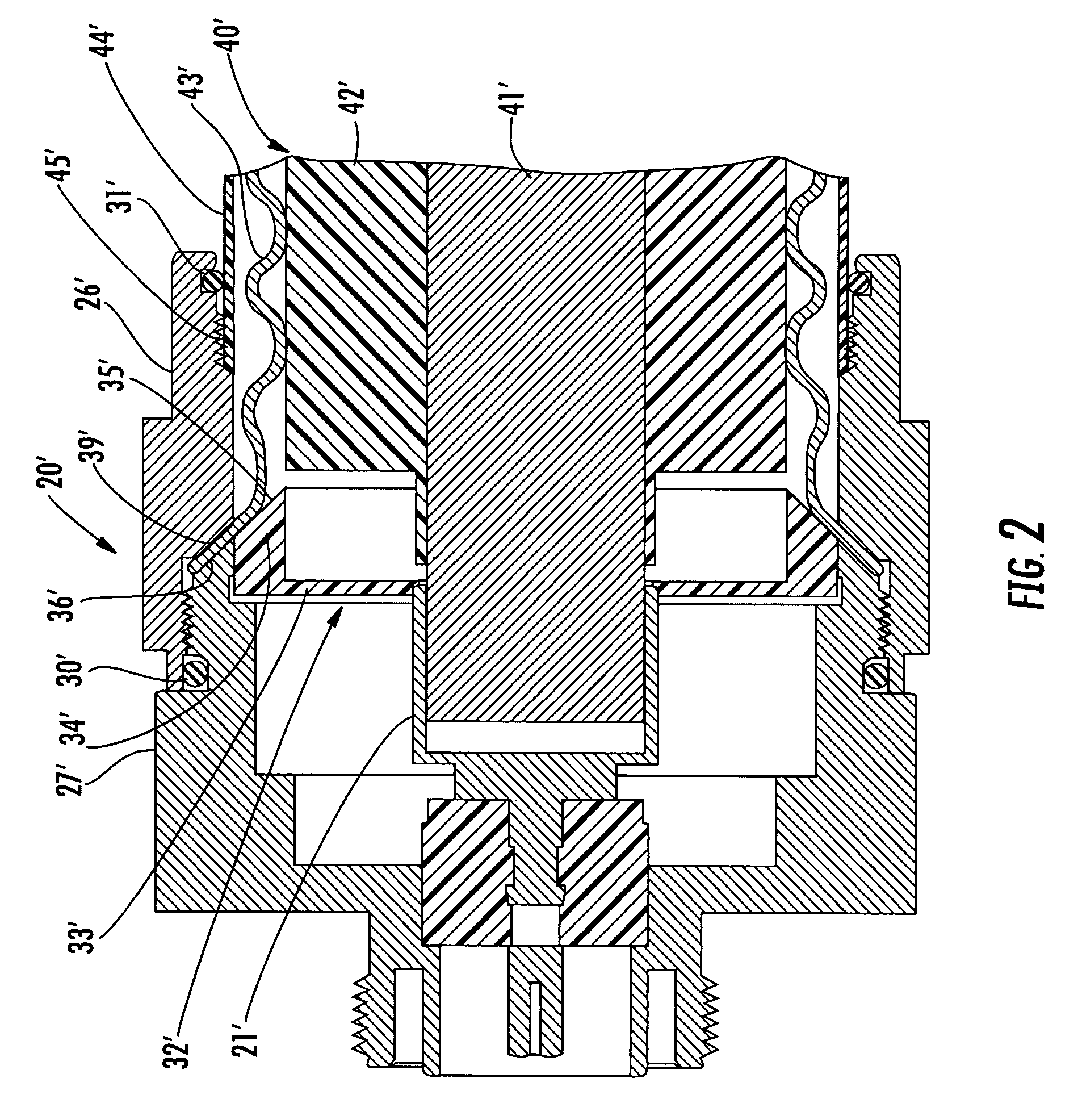
[0022]The present invention will now be described more fully hereinafter with reference to the accompanying drawings, in which a preferred embodiment of the invention is shown. This invention may, however, be embodied in many different forms and should not be construed as limited to the embodiments s et forth herein. Rather, these embodiments are provided so that this disclosure will be thorough and complete, and will fully convey the scope of the invention to those skilled in the art. Like numbers refer to like elements throughout and prime and multiple prime notation are used to indicate similar elements in alternative embodiments.

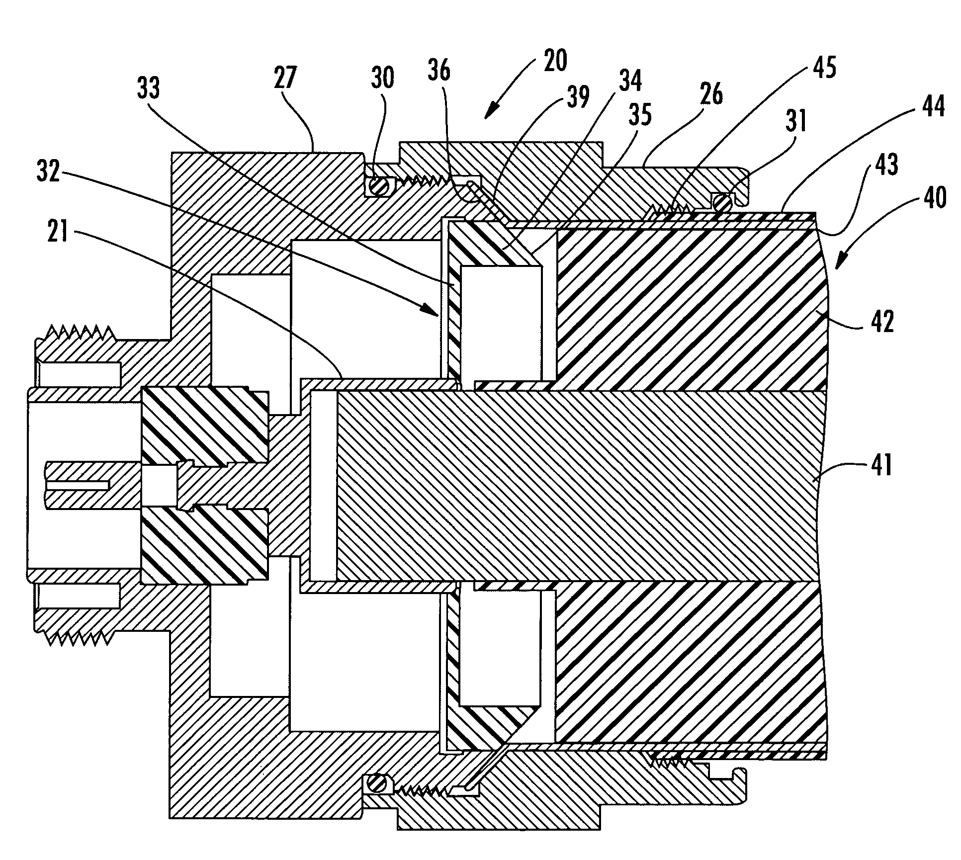
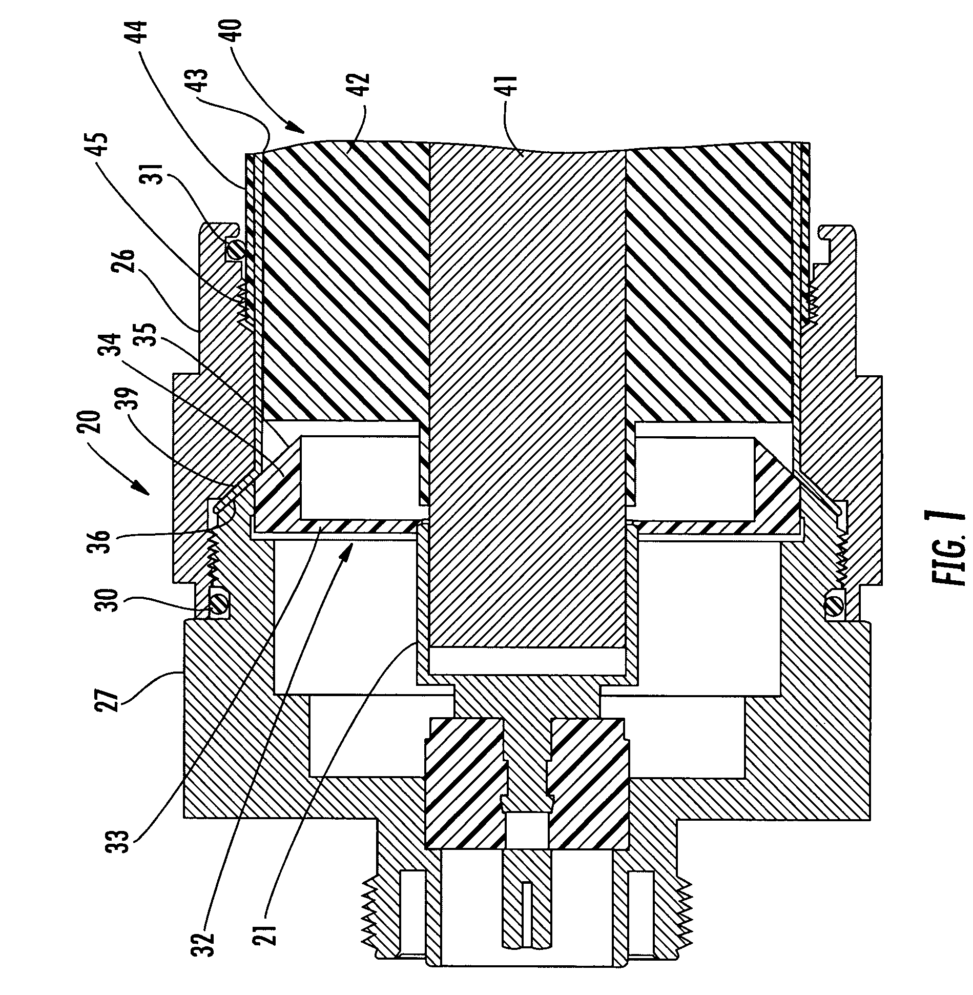
[0023]Referring now initially to FIG. 1, the coaxial connector 20 in accordance with the present invention is now described. The connector 20 is installed onto the den of a coaxial cable 40 that illustratively includes an inner conductor 41, a dielectric foam layer 42 surrounding the inner conductor, an outer conductor 43 surrounding the dielectric layer...


PUM


Abstract

The coaxial cable connector includes a connector housing defining a radially outer ramp portion. The coaxial cable connector may also include an insulator member in the connector housing. The insulator member defines a radially inner ramp portion aligned with the radially outer ramp portion. The coaxial cable connector may include a back nut defining an opposing ramp opposite the outer ramp portion so that the radially inner and outer ramp portions may flare an end of the outer conductor as the coaxial cable is advanced into the connector housing. At least the radial outer ramp portion may cooperate with the opposing ramp of the back nut to clamp the flared end of the outer conductor therebetween.

Description

RELATED APPLICATION[0001]This application is based upon and claims priority to now abandoned provisional application No. 60 / 780,106 filed Mar. 8, 2006 and to now abandoned provisional application No. 60 / 745,500 filed Apr. 24, 2006. The entire subject matter of these provisional applications is incorporated herein by reference in its entirety.FIELD OF THE INVENTION[0002]The present invention relates to the field of cables and connectors, and, more particularly, to a connector for coaxial cables and associated methods.BACKGROUND OF THE INVENTION[0003]Coaxial cables are widely used to carry high frequency electrical signals. Coaxial cables enjoy a relatively high bandwidth, low signal losses, are mechanically robust, and are relatively low cost. One particularly advantageous use of a coaxial cable is for connecting electronics at a cellular or wireless base station to an antenna mounted at the top of a nearby antenna tower. For example, the transmitter located in an equipment shelter m...

Claims


Application Information

Patent Timeline
Patent Type & Authority Patents(United States)
IPC IPC(8): H01R9/05
CPCH01R9/0521H01R43/28H01R9/05H01R11/26
Inventor VACCARO, RONALD A.
Owner COMMSCOPE INC
Why Eureka
Try Eureka