Dual gate transistor keeper dynamic logic

a transistor and dynamic logic technology, applied in logic circuits, logic functions, pulse techniques, etc., can solve the problems of limiting the robustness of dynamic circuits, consuming power, and difficult to hold the logic state of dynamic nodes after evaluation,

Active Publication Date: 2008-02-26
MARVELL ASIA PTE LTD
View PDF11 Cites 9 Cited by
  • Summary
  • Abstract
  • Description
  • Claims
  • Application Information

AI Technical Summary

Problems solved by technology

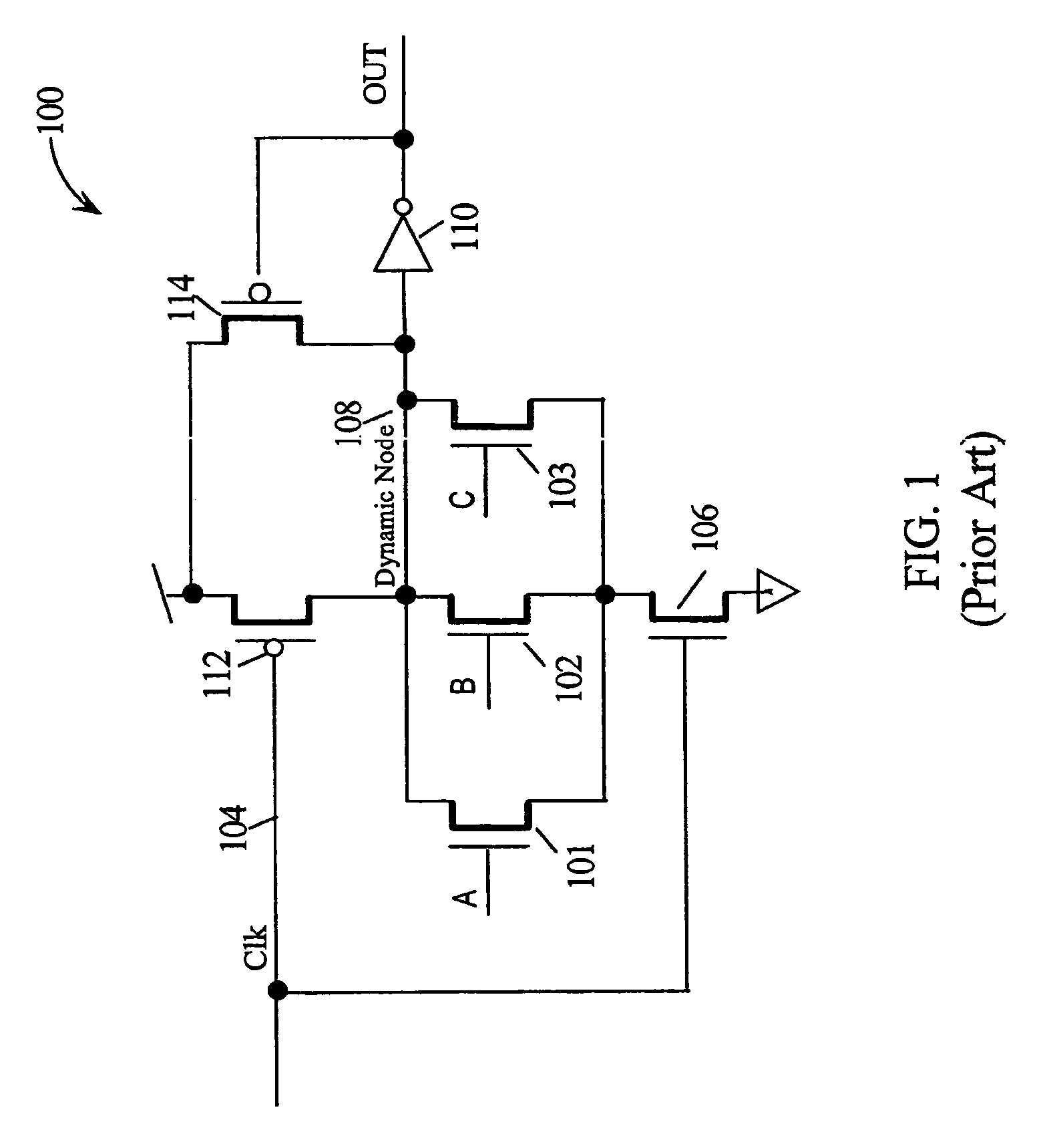
However, the switching of the output node with the toggling of the phase of the clock each cycle may consume power even when the logical value of the output is otherwise unchanged.
When a select device connects the intermediate nodes to the dynamic node, leakage current may make it difficult to hold the logic state on the dynamic node after completion of evaluation.
The sharp increase of leakage currents in scaled technologies severely limits the robustness of dynamic circuits, especially for high fan in wide dynamic gates, commonly employed in the performance critical units of high-performance microprocessors.
However, the use of a strong (large) keeper results in severe contention during the evaluation phase causing significant degradation of the performance.
While effective, both of these techniques result in increased area of the dynamic logic gate and added capacitance to the dynamic node which increase cost and degrade performance.

Method used


Image

  • Dual gate transistor keeper dynamic logic
  • Dual gate transistor keeper dynamic logic
  • Dual gate transistor keeper dynamic logic

Examples


Embodiment Construction

[0019]In the following description, numerous specific details are set forth to provide a thorough understanding of the present invention. For example, specific logic functions and the circuitry for generating them may be described; however, it would be recognized by those of ordinary skill in the art that the present invention may be practiced without such specific details. In other instances, well-known circuits have been shown in block diagram form in order not to obscure the present invention in unnecessary detail. Refer now to the drawings wherein depicted elements are not necessarily shown to scale and wherein like or similar elements are designated by the same reference numeral by the several views.

[0020]Refer now to the drawings wherein depicted elements are not necessarily shown to scale and wherein like or similar elements are designated by the same reference numeral through the several views.

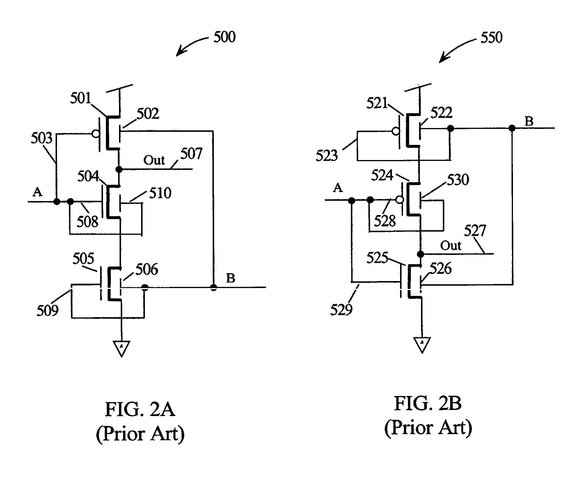
[0021]Dual or double gate FET devices have been described in the literature. Two r...


PUM


Abstract

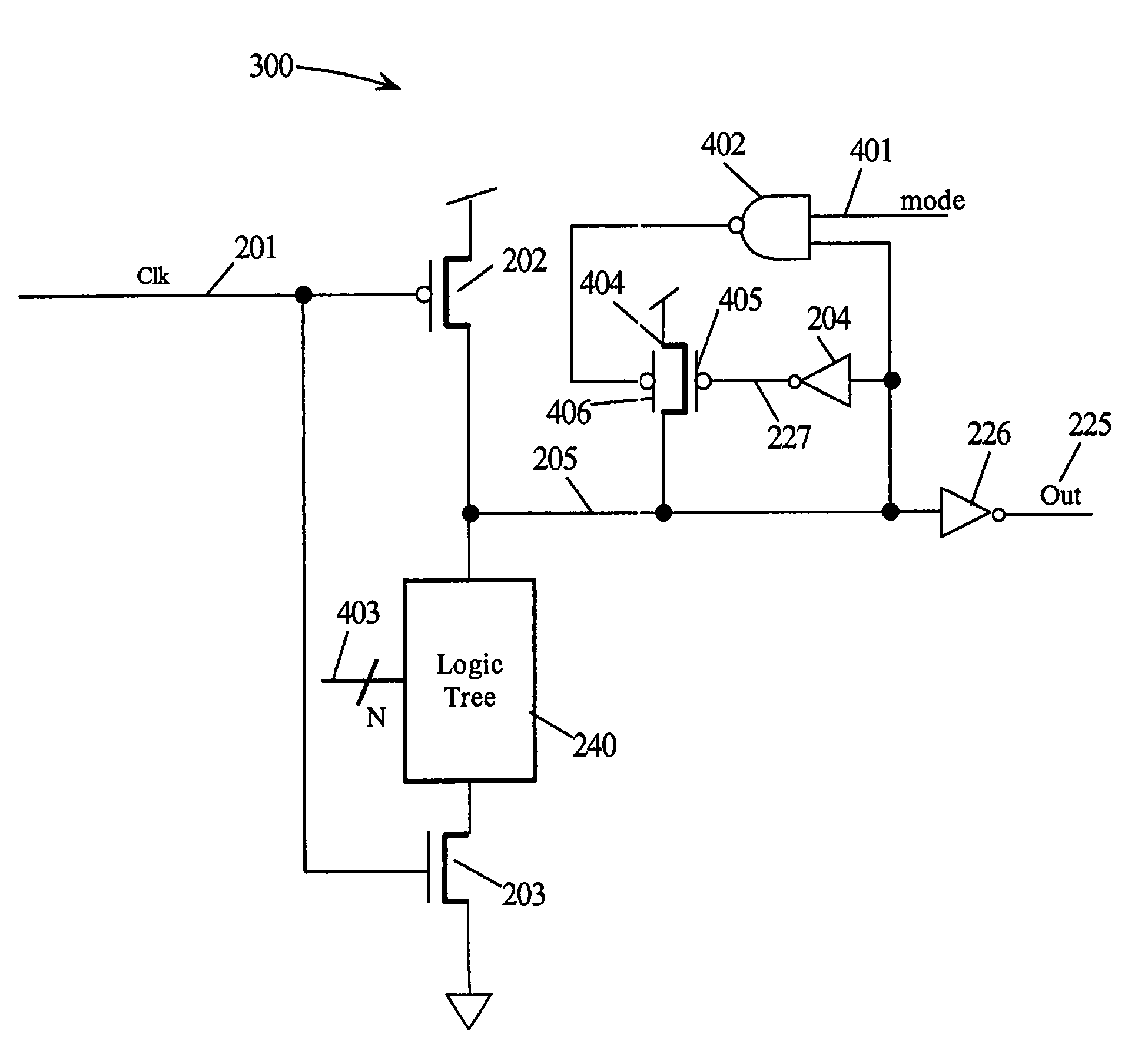
A dynamic logic gate has a device for charging a dynamic node during a pre-charge phase of a clock. A logic tree evaluates the dynamic node with a device during an evaluate phase of the clock. The dynamic node has a keeper circuit comprising an inverter with its input coupled to the dynamic node and its output coupled to the back gate of a dual gate PFET device. The source of the dual gate PFET is coupled to the power supply and its drain is coupled to the dynamic node forming a half latch. The front gate of the dual gate PFET is coupled to a logic circuit with a mode input and a logic input coupled back to a node sensing the state of the dynamic node. The mode input may be a slow mode to preserve dynamic node state or the clock delayed that turns ON the strong keeper after evaluation.

Description

GOVERNMENT RIGHTS[0001]This invention was made with Government support under DARPA, NBCH3039004, BGR W0132280. THE GOVERNMENT HAS CERTAIN RIGHTS IN THIS INVENTION.TECHNICAL FIELD[0002]The present invention relates to dynamic logic circuits, and in particular, to dynamic logic circuits using a timed keeper for holding the state of the dynamic node.BACKGROUND INFORMATION[0003]Modern data processing systems may perform Boolean operations on a set of signals using dynamic logic circuits. Dynamic logic circuits are clocked. During the precharge phase of the clock, the circuit is precondition, typically precharging an internal node (dynamic node) of the circuit by coupling to a power supply rail. During an evaluate phase of the clock, the Boolean function being implemented by the logic circuit is evaluated in response to the set of input signal values appearing on the inputs during the evaluate phase. (For the purposes herein, it suffices to assume that the input signals have settled to t...

Claims


Application Information

Patent Timeline
Patent Type & Authority Patents(United States)
IPC IPC(8): H03K19/20H01L21/84H03K19/094
CPCH03K19/0963
Inventor CHUANG, CHING-TEKIM, KEUNWOOKUANG, JENTE BENEDICTNOWKA, KEVIN JOHN
Owner MARVELL ASIA PTE LTD
Why Eureka
Try Eureka