Dual band space-fed array

a space-fed array and dual-band technology, applied in the direction of antenna details, space-fed arrays, antennas, etc., can solve the problems of weight and power limitations of airborne sensor arrays

Active Publication Date: 2008-02-26
RAYTHEON CO
View PDF10 Cites 35 Cited by
  • Summary
  • Abstract
  • Description
  • Claims
  • Application Information

AI Technical Summary

Problems solved by technology

Airborne sensor arrays provide challenges in terms of weight and power limitations.

Method used


Image

  • Dual band space-fed array
  • Dual band space-fed array
  • Dual band space-fed array

Examples


Embodiment Construction

[0018]In the following detailed description and in the several figures of the drawing, like elements are identified with like reference numerals. The figures are not to scale, and relative feature sizes may be exaggerated for illustrative purposes.

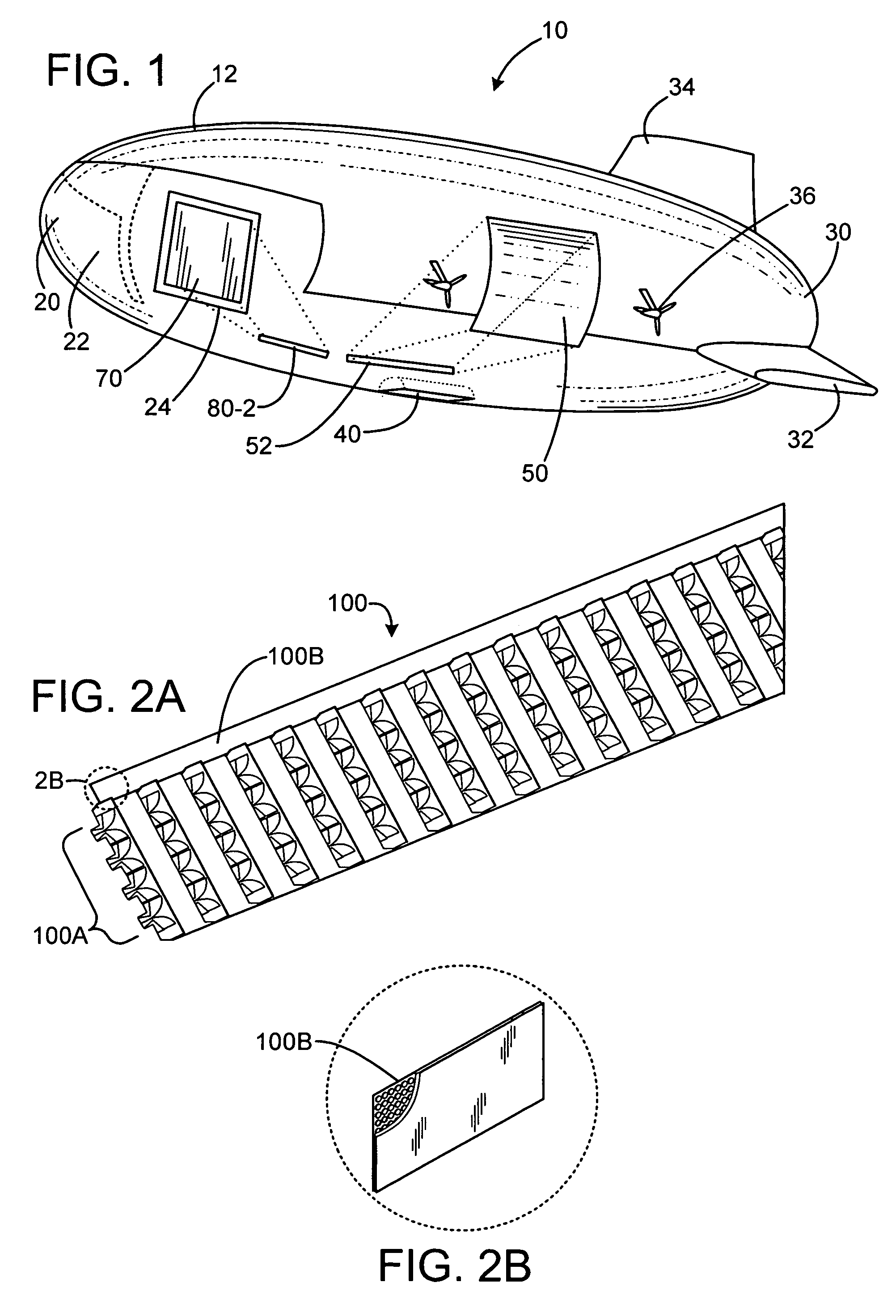
[0019]An exemplary vehicle on which a sensor or antenna array may be installed is an airship, i.e. a lighter-than-air craft. Antenna arrays and components described below are not limited to this application, however. For the sake of this example, the airship may be a stratospheric craft on the order of 300 meters in length. The airship may be preferably semi-rigid or non-rigid in construction. The airship may include an outer balloon structure or skin which may be inflated, with internal ballonets filled with air to displace helium in the airship for airlift control.

[0020]FIG. 1 shows an exemplary airship in simplified isometric view. The airship 10 includes an outer skin surface 12, a nosecone region 20, a stern region 30, horizontal fins...


PUM


Abstract

A dual-band, space fed antenna array includes a feed array with a first set of feed radiators for operation in a first frequency band of operation and a second set of feed radiators for operation in a second frequency band of operation. A primary array lens assembly is spaced from and illuminated by the feed array. The primary array lens includes a first set of radiator elements and a second set of radiator elements operable in the first frequency band of operation. The primary array lens assembly also includes a third set of radiator elements and a fourth set of radiator elements operable in the second frequency band of operation.

Description

[0001]This invention was made with Government support under Contract No. HR0011-04-C-0096 awarded by the Defense Advanced Research Projects Agency. The Government has certain rights in this invention.BACKGROUND[0002]Airborne sensor arrays provide challenges in terms of weight and power limitations. Reducing weight and power requirements is a typical objective for airborne and space sensor arrays.SUMMARY OF THE DISCLOSURE[0003]An exemplary embodiment of a dual-band, space fed antenna array includes a feed array comprising a first set of feed radiators for operation in a first frequency band of operation and a second set of feed radiators for operation in a second frequency band of operation. A primary array lens assembly is spaced from and illuminated by the feed array. The primary array lens includes a first set of radiator elements and a second set of radiator elements operable in the first frequency band of operation. The primary array lens assembly further includes a third set of...

Claims


Application Information

Patent Timeline
Patent Type & Authority Patents(United States)
IPC IPC(8): H01Q19/06H01Q5/42
CPCH01Q1/1292H01Q1/286H01Q3/46H01Q13/08H01Q5/42H01Q21/0018H01Q21/064H01Q21/065H01Q13/085
Inventor LEE, JAR J.QUAN, CLIFTONLIVINGSTON, STANLEY W.
Owner RAYTHEON CO
Why Eureka
Try Eureka