Per-pixel output luminosity compensation

a technology of luminosity compensation and output light, applied in the field of image generation, can solve the problems of difficult to achieve precise alignment with the screen, inability to uniformly illuminate the display device, and inability to change ambient lighting to achieve uniform illumination

Active Publication Date: 2008-02-26
NVIDIA CORP
View PDF4 Cites 64 Cited by
  • Summary
  • Abstract
  • Description
  • Claims
  • Application Information

AI Technical Summary

Benefits of technology

[0008]The target surface may include a polygon having vertices, and one or more of the vertices may be associated with one of the image texels of the image texture, and a user interface may be provided enabling the user to modify the shape of the target surf

Problems solved by technology

Such distortions commonly occur with tabletop projectors, where precise alignment with a screen is difficult to achieve.
Ambient lighting, however, is not necessarily uniform over a surface on which the image is to be displayed.
A standard brightness control does not address such nonuniformity, and changing the ambient lightin

Method used


Image

  • Per-pixel output luminosity compensation
  • Per-pixel output luminosity compensation
  • Per-pixel output luminosity compensation

Examples


Embodiment Construction

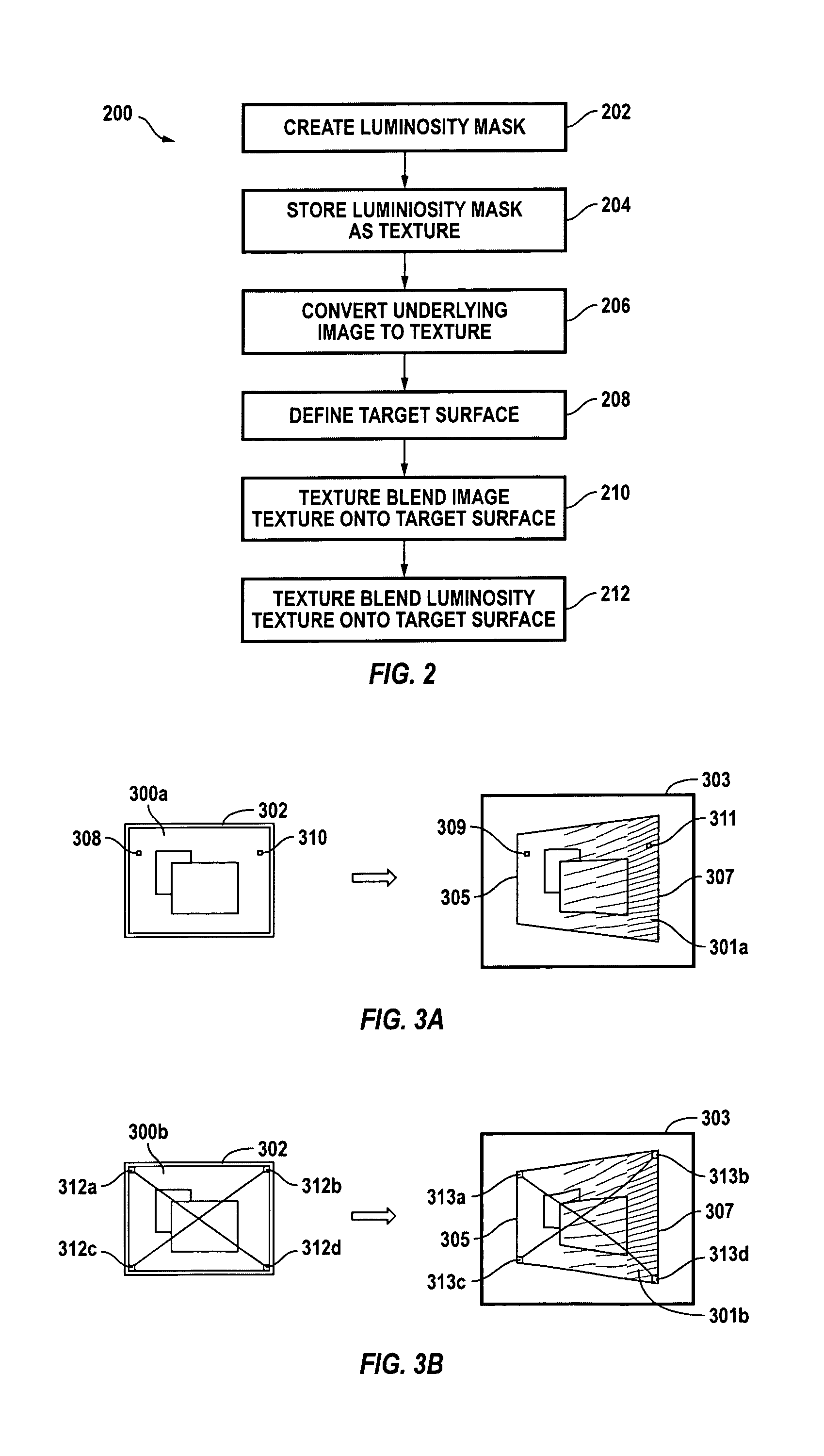
[0023]Embodiments of the present invention provide a per-pixel luminosity adjustment using a luminosity mask applied as a texture to pixel data of an underlying image. This texture blending operation can be performed by a graphics processor and controlled by software so that no additional control circuitry or other hardware is required, thereby offering an economical solution to problems of nonuniform illumination. Luminosity compensation according to the present invention is not limited to correcting for nonuniform illumination. A wide array of other effects can also be created using systems and methods described herein.

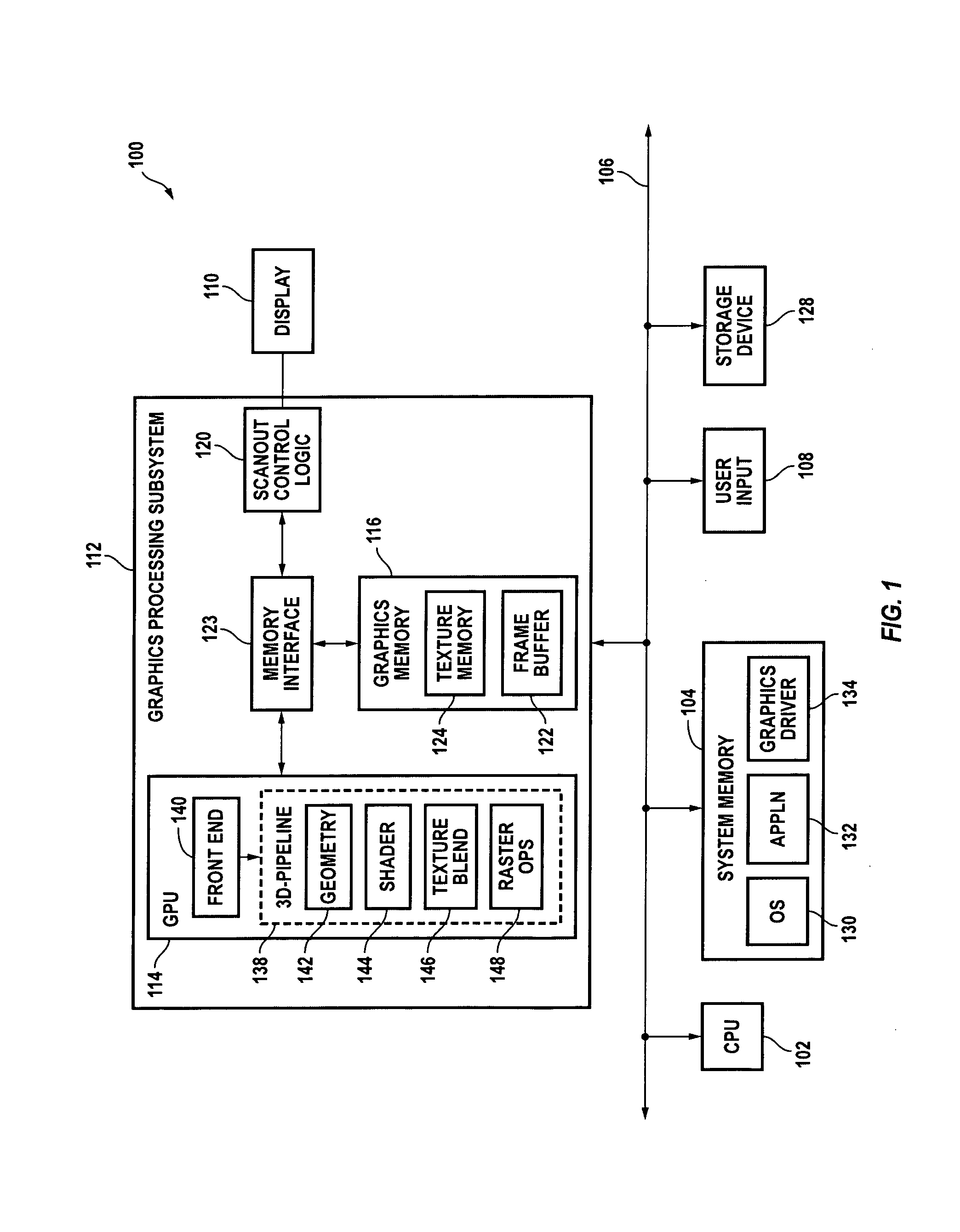
[0024]FIG. 1 is a simplified block diagram of a computer system 100 according to an embodiment of the present invention. Computer system 100 includes a central processing unit (CPU) 102 and a system (or main) memory 104 communicating via a bus 106. User input is received from one or more user input devices 108 (e.g., keyboard, mouse) coupled to bus 106. Visual outpu...


PUM


Abstract

Per-pixel luminosity adjustment uses a luminosity mask applied as a texture. In one embodiment, a luminosity texture is defined. Pixel data of an underlying image is converted to an image texture. The image texture is blended onto a target surface. The luminosity texture is also blended onto the target surface, thereby generating luminosity compensated pixel data for the image.

Description

CROSS-REFERENCES TO RELATED APPLICATIONS[0001]The present disclosure is related to the following commonly-assigned now abandoned U.S. Patent Applications: No. 60 / 384,663, filed May 31, 2002, entitled “Method and Apparatus for Display Image Adjustment”; and 60 / 463,759, filed Apr. 17, 2003, entitled “Method and Apparatus for Display Image Adjustment”. The respective disclosures of these applications are incorporated herein by reference for all purposes.BACKGROUND OF THE INVENTION[0002]The present invention relates generally to image generation and in particular to systems and methods for compensating output luminosity of an image on a pixel-by-pixel basis.[0003]The appearance of an image displayed by a display device (e.g., a monitor or projection system) depends in part on environmental factors not inherent in the image generation system or the display device. For example, consider an image projected onto a screen by a projector. If the optical axis of the projector is not normal to ...

Claims


Application Information

Patent Timeline
IPC IPC(8): G06T15/50
CPCG06T15/04G06T15/503
Inventor CLARK, RICHARDMOREY, DAVID R.
Owner NVIDIA CORP
Why Eureka
Try Eureka