Magnetic head assembly

a head assembly and magnetic technology, applied in the field of magnetic head assembly, can solve the problems of air flow, difficult positioning, and vibration of the magnetic head assembly on which the magnetic head is mounted, and achieve the effect of suppressing vibrations

Inactive Publication Date: 2008-02-26
TOSHIBA STORAGE DEVICE CORP
View PDF16 Cites 19 Cited by
  • Summary
  • Abstract
  • Description
  • Claims
  • Application Information

AI Technical Summary

Benefits of technology

[0030]A preferred embodiment of the above third aspect of the invention is characterized in that the constraining layer of the damping material is stainless steel, and the elastic layer is a VEM.
[0031]This invention enables suppression of vibrations in a magnetic head assembly on which a magnetic head is mounted, caused by the effects of the flow of air arising from the high-speed rotation of the magnetic disk in the magnetic disk device.

Problems solved by technology

However, in a magnetic disk device the high-speed rotation of the magnetic disk causes air flow, and the magnetic head assembly on which the magnetic head is mounted undergoes vibrations.
In a magnetic disk device in which submicron positioning is required, the influence of air flow and vibrations makes accurate positioning difficult, and causes detracking.
If detracking occurs frequently, the frequency of occurrence of data record / playback errors is increased, and the data transfer rate declines.
However, although it is possible tot suppress torsion mode vibrations in the load beam 3 of a magnetic head assembly by affixing such damping material, suppression of other vibration modes cannot be expected.
Moreover, randomly affixing the damping material in a magnetic head assembly incurs increased manufacturing costs and so is undesirable.
Randomly affixing damping material results in increases in the moment of inertia of rotation centered on the actuator of the magnetic head assembly, and so is undesirable.

Method used


Image

  • Magnetic head assembly
  • Magnetic head assembly
  • Magnetic head assembly

Examples


Embodiment Construction

[0049]Below, aspects of the invention are explained referring to the drawings. However, the technical scope of the invention is not limited to these aspects, but extends to the inventions described in the scope of claims, and to inventions equivalent thereto.

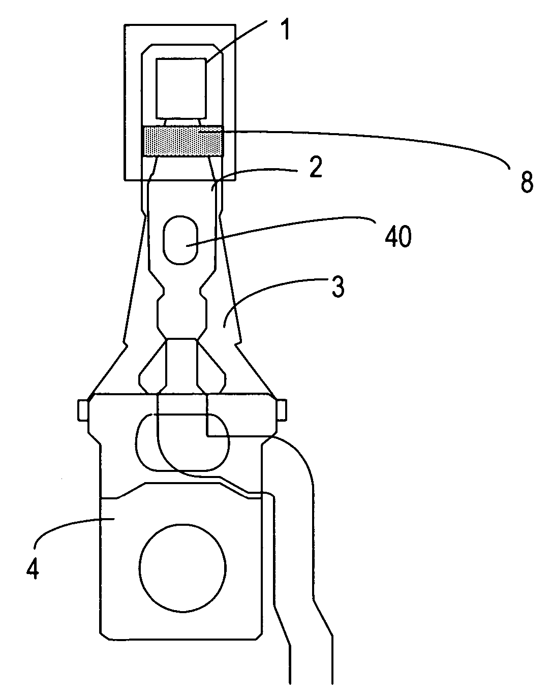
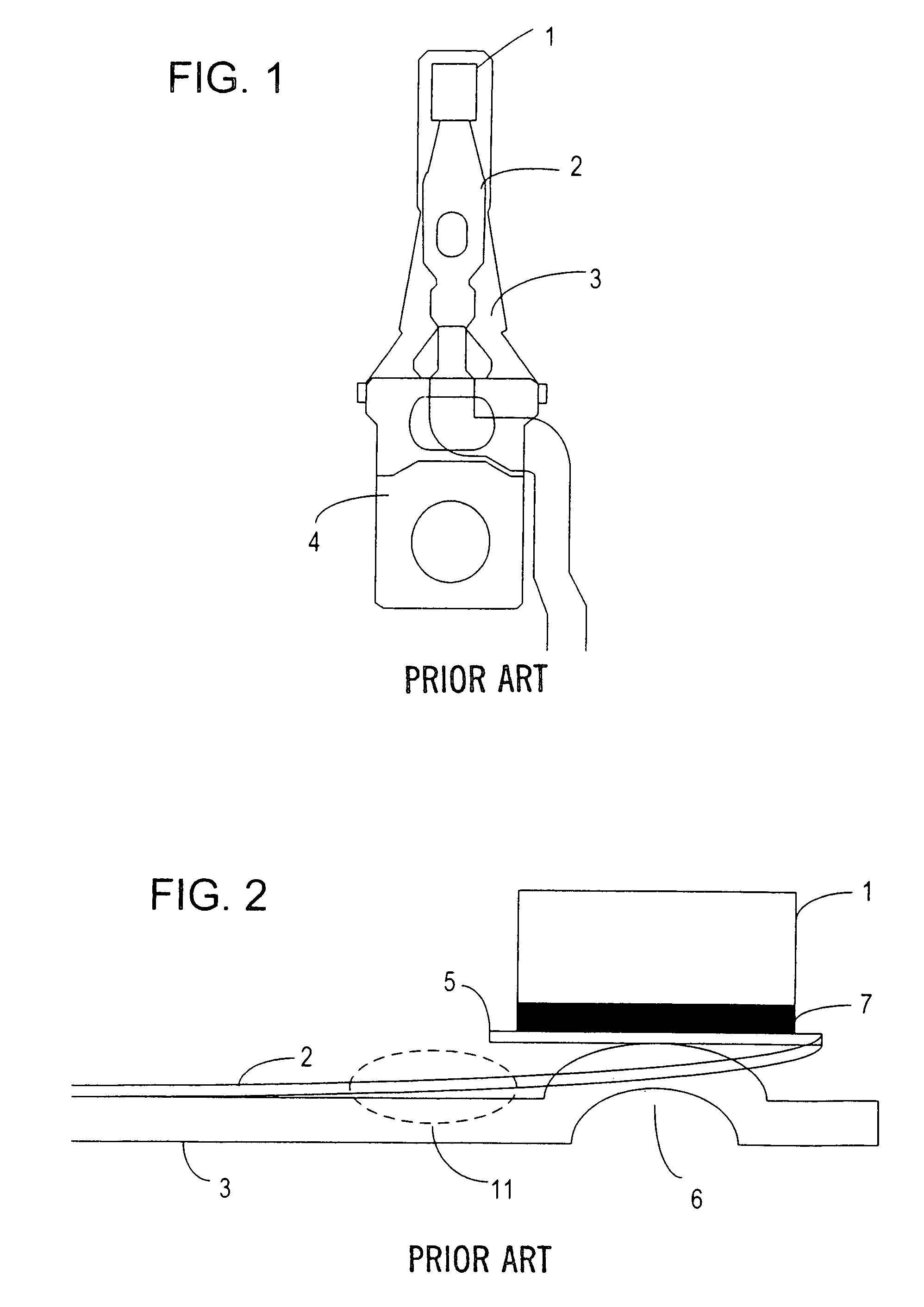
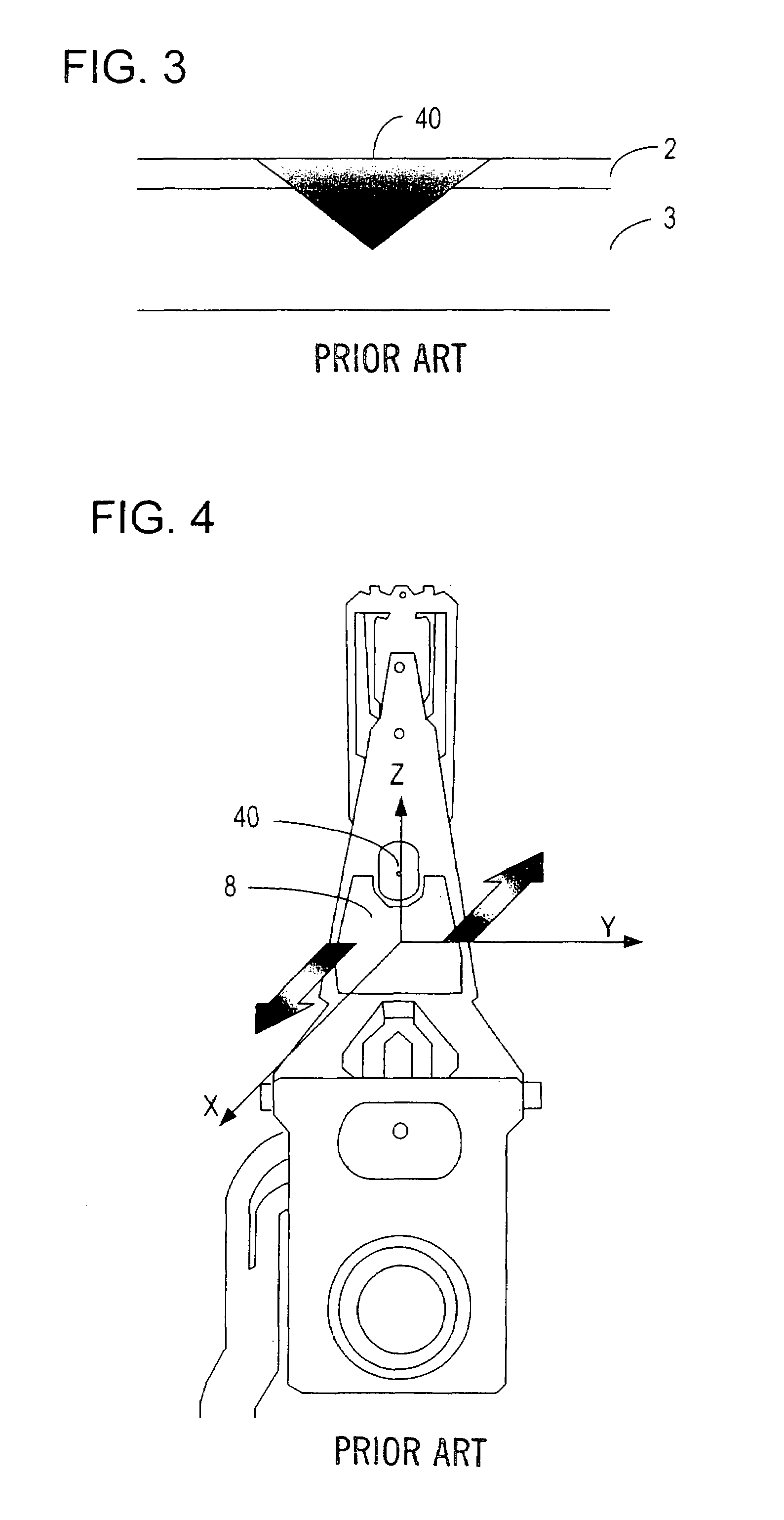
[0050]FIG. 5 shows torsion mode vibrations in a flexure. As shown in FIG. 5, during operation of the magnetic disk device the magnetic head 1 and the gimbal support portion 11 of the flexure 2 vibrate in opposite phase in the X-axis direction, to constitute torsion mode vibration.

[0051]FIG. 6 shows the configuration of the magnetic head assembly in a first aspect of the invention. A damping material 8 is installed at the gimbal support portion 11 adjacent to the magnetic head 1, affixed so that the flexure 2 is enclosed between the damping material 8 and the load beam 3, of comparatively high rigidity. By affixing the damping material 8 at a position closer to the magnetic head than the laser welded portion 40, an effect in supp...


PUM

PropertyMeasurementUnit
thicknessesaaaaaaaaaa
heat resistanceaaaaaaaaaa
dielectric constantaaaaaaaaaa

Abstract

Vibrations in a magnetic head assembly equipped with a magnetic head, caused by the effects of the flow of air arising from the high-speed rotation of a magnetic disk, can be suppressed by affixing a damping material to the magnetic head assembly. As a result, accurate positioning is possible with high reliability, the frequency of occurrence of errors during data recording and playback can be suppressed, high data transfer rates can be maintained, and high recording densities for a magnetic disk device can be realized.

Description

BACKGROUND OF THE INVENTION[0001]1. Field of the Invention[0002]This invention relates to a magnetic head assembly in a magnetic disk device, and in particular to a magnetic head assembly which suppresses vibrations.[0003]2. Description of the Related Art[0004]A magnetic disk device causes a magnetic disk, comprising ferromagnetic material, to rotate, and by scanning a magnetic head over the magnetic disk records and reproduces information; such devices are widely used as auxiliary storage devices in computers.[0005]With the expansion of magnetic disk device capacities in recent years, there has been increased need for higher recording densities. Methods of raising recording densities include methods to increase the linear recording density in the track direction, and methods to raise the recording density in the radial direction of the magnetic disk by reducing the track width and track pitch. In order to raise the recording density through the latter methods in particular, a magne...

Claims


Application Information

Patent Timeline
Patent Type & Authority Patents(United States)
IPC IPC(8): G11B5/48
CPCG11B5/4826G11B5/4833G11B33/08G11B21/21
Inventor KIDO, TAKUMASUKAGAWA, TOMOOARUGA, KEIJI
Owner TOSHIBA STORAGE DEVICE CORP
Why Eureka
Try Eureka