
Method of simulating the sedimentary deposition in a basin respecting the thicknesses of the sedimentary sequences

a sedimentary sequence and simulating method technology, applied in the direction of instruments, analogue processes for specific applications, electric/magnetic computing, etc., can solve the problems of never succeeding, hypothesis may appear too restrictive, and cannot ensure a satisfactory agreement between the reality observed and the result of the model

Active Publication Date: 2008-02-26
INST FR DU PETROLE
View PDF9 Cites 61 Cited by
  • Summary
  • Abstract
  • Description
  • Claims
  • Application Information

AI Technical Summary

Benefits of technology

The invention is a method for creating a model of the sedimentary layers in a basin and the changes in the sediment supply over time. This is done by using data from seismic surveys and well data, along with information about the initial topography of the basin and the distribution of the sediment supply. The method involves solving transportation equations to calculate the thickness of each layer and updating the thicknesses of each layer as new data is collected. The method allows for a more accurate understanding of the sedimentary sequences and the changes in the sediment supply over time.

Problems solved by technology

Furthermore, although these methods improve the agreement between the reality observed and the model obtained, these methods do not ensure a satisfactory agreement between the reality observed and the result of the model.
This also applies to an automatic procedure and can never succeed if the data initially proposed by the user are too far from the solution.
This hypothesis may appear to be too restrictive in some situations, notably when the diffusion coefficients characterizing the sedimentary transport efficiency become too small, which is the case in the depositional geometries exhibiting clinoforms, which translate deposition of a sediment as soon as it enters the marine environment, without further reworking.

Method used


Image

  • Method of simulating the sedimentary deposition in a basin respecting the thicknesses of the sedimentary sequences
  • Method of simulating the sedimentary deposition in a basin respecting the thicknesses of the sedimentary sequences
  • Method of simulating the sedimentary deposition in a basin respecting the thicknesses of the sedimentary sequences

Examples


application example

[0155]First, a synthetic example on a single layer of a 3D basin is constructed, allowing to appreciate the results of the invention. Domain Ω is a rectangle (0,Lx)×(0,Ly) with Lx=100 km and Ly=50 km. The incoming flows at the boundaries are −1,5 m2 / year on side x=0, −0,75 m2 / year on side y=50 km, and the outgoing flows are zero on the other two sides. The sediments have two lithologies (L=2) of diffusion coefficients k1,c=500 m2 / year, k2,c=50 m2 / year, k1,m=50 m2 / year and k2,m=5 m2 / year. The incoming fractional flows at x=0 and y=50 km are 0,5. The initial composition of the basin is 0.5. The sequence duration is 10 Ma. The calculation grid is uniform Cartesian of size 40×20 cells, and the time interval is uniform, equal to 1 Ma. The synthetic example is constructed considering an initial bathymetry defined, in km, by b0(x)=A0(x)=100(1−cos π(x−y)). The thickness of the first layer (l=0) to be calibrated is obtained by a calculation of the instationary model for an accommodation at t...


PUM


Abstract

The method of the invention allows, by means of an iterative inversion algorithm, prediction of the spatial distribution of the lithologic composition of sediments deposited in a sedimentary basin during a geologic time interval, and the temporal evolution of the depositional profile throughout filling of the basin, while respecting exactly the thicknesses of the sedimentary sequences measured otherwise which is useful for locating hydrocarbon reservoirs. Input data of thickness maps of the sedimentary layer, location and composition of the sediment supply at the boundaries of the sedimentary basin, and physical parameters characterizing transport of the sediments during the period of consideration are applied to an iterative inversion loop initialized by the accommodation provided by a stationary multilithologic diffusive model which works as a fixed-point algorithm correcting the accommodations by means of a preconditioning of the residue on the sequence thicknesses obtained by an instationary model.

Description

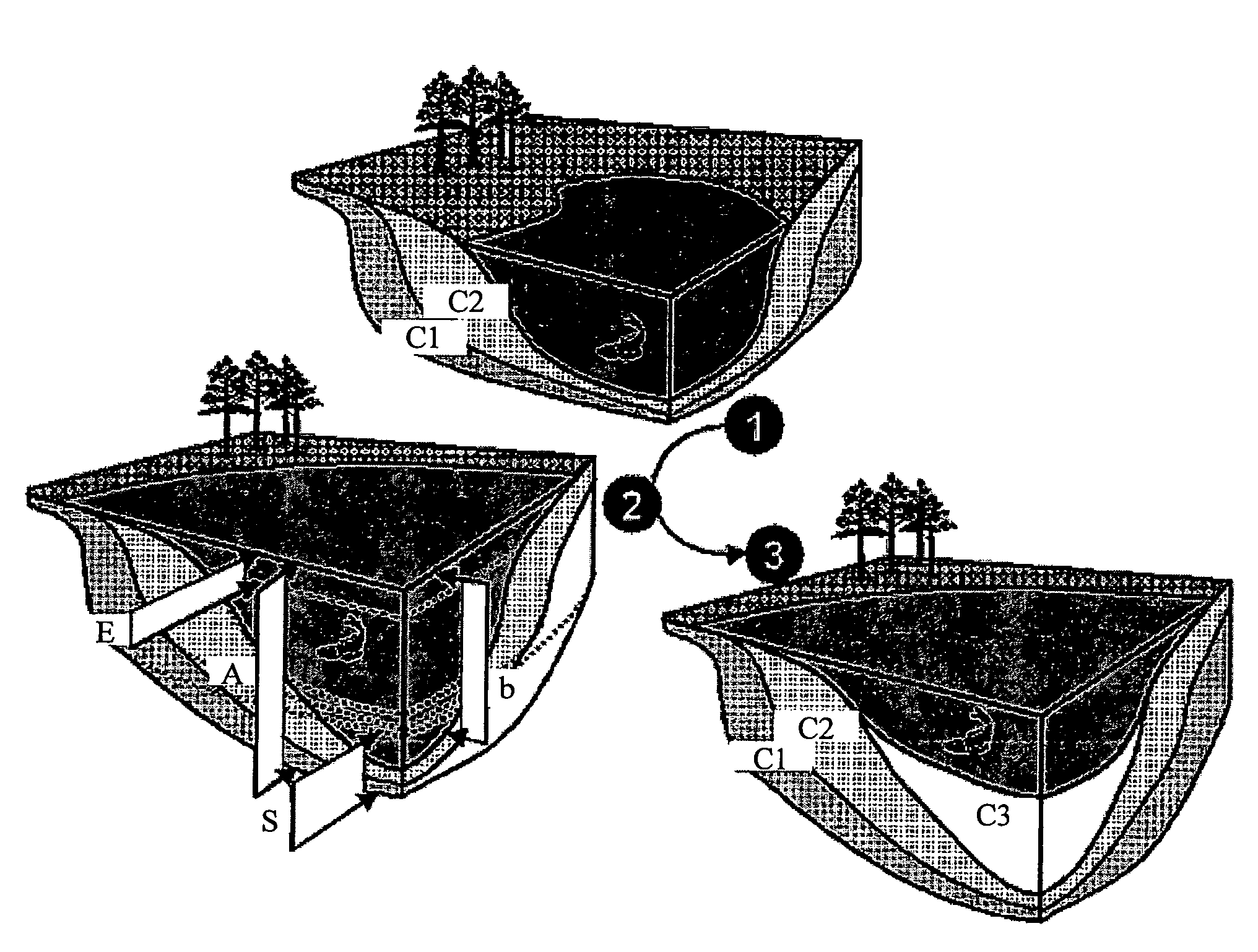
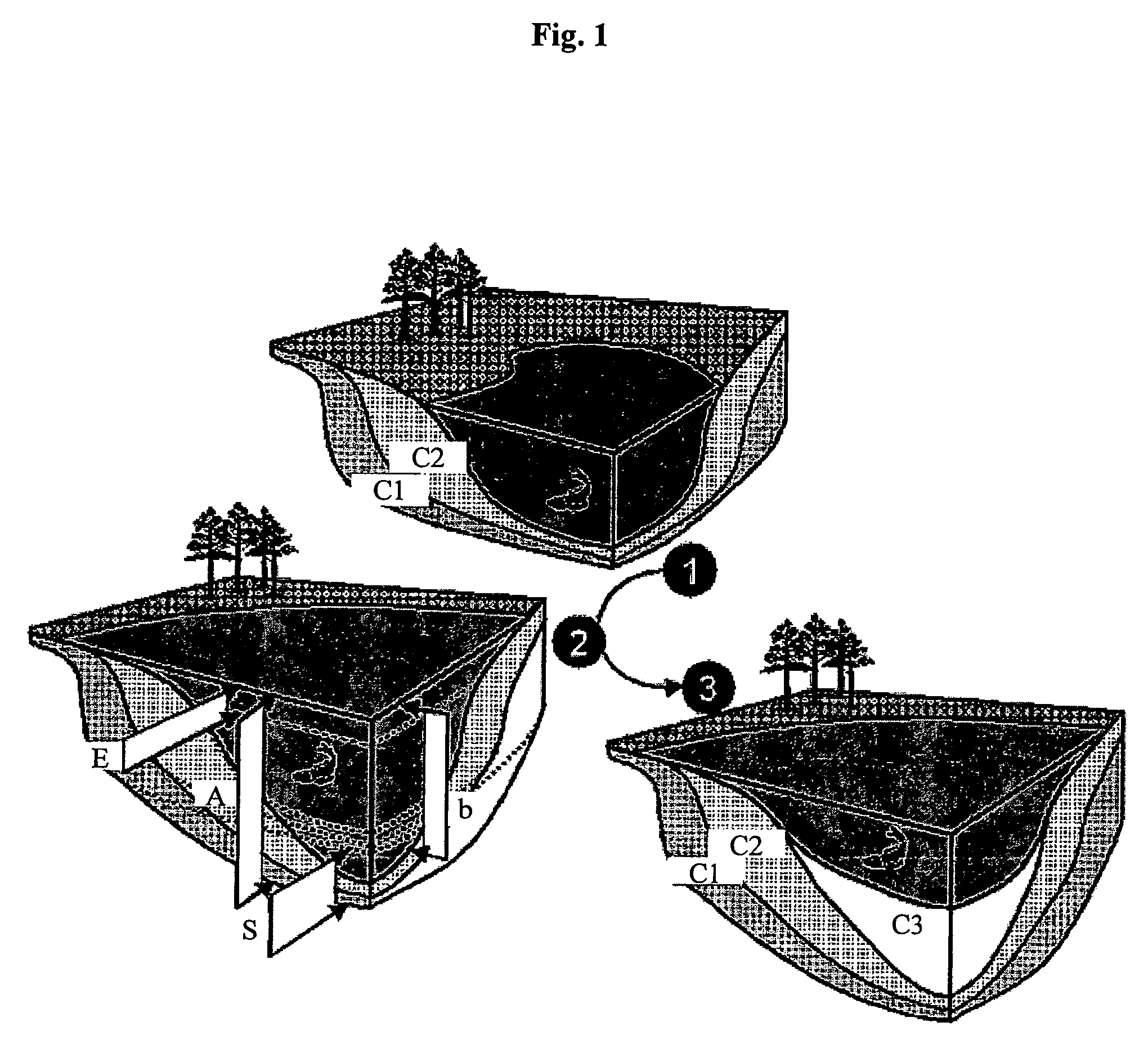
BACKGROUND OF THE INVENTION[0001]1. Field of the Invention[0002]The present invention relates to a method for establishing a three-dimensional map of the spatial distribution of the lithologic composition of sediments deposited in a sedimentary basin during a given geologic time interval, as well as the temporal evolution of the depositional profile throughout filling of the basin, while respecting exactly the thicknesses of the sedimentary sequences measured otherwise.[0003]FIG. 1 shows three filling stages of a sedimentary basin. The fill of a sedimentary basin has superposed layers (C1, C2 and C3), also referred to as sedimentary sequences, which correspond each to the deposition of sediments during a sub-time interval of the geologic period required for filling of the basin. Each layer is thus limited by a lower surface (referred to as “base” of the sequence) and an upper surface (referred to as “top” of the sequence). Thus, the top of a sequence coincides with the base of the n...

Claims


Application Information

Patent Timeline
Patent Type & Authority Patents(United States)
IPC IPC(8): G01V1/00G06G7/48G01V1/28G01V11/00
CPCG01V1/282G01V11/00G01V2210/661
Inventor MASSON, ROLANDCACAS, MARIE-CHRISTINEDOBRANSZKY, GABRIELA
Owner INST FR DU PETROLE
Learn More