System and method for remote asset monitoring

a technology of system and method, applied in the field of system and method for remote asset monitoring, can solve the problems of low system reliability, low system reliability, and low degree of automation, and achieve the effects of reducing system reliability, improving system reliability, and improving system reliability

Inactive Publication Date: 2008-02-26
WORLDTELEMETRY
View PDF51 Cites 44 Cited by
  • Summary
  • Abstract
  • Description
  • Claims
  • Application Information

AI Technical Summary

Problems solved by technology

While electronically readable instrumentation may be readily available for such monitoring, there are few options presently available for remote monitoring of such instrumentation.
Either way, the periodic checking of the gauge is at a minimum inconvenient, unreliable and possibly costly.
While a vast improvement over manual monitoring, these systems still suffer from a number of limitations.
By way of example, limitations include: there is no means for communicating back to the tank for purposes of control, special monitoring, or programming changes; transmissions occur at a fixed rate regardless of the need to update or changing conditions, thereby wasting transmitter battery life; transmissions occur asynchronously and thus, in an area with multiple transmitters, some transmissions will occasionally overlap, corrupting the data from both transmitters; etc.
While these limitations could be overcome in a system having bi-directional operation, providing a receiver at the monitoring location would further reduce battery life.
Providing continuous power to a radio receiver in the battery powered unit at the tank would simply not be practical.
If electrical service and a phone line were provided at the tank, there would obviously be no concerns of battery usage, however this situation would substantially increase the cost and complexity of a tank installation.
In addition, having electrical devices in close proximity to the tank would increase the risk of fire from leaks or from the venting of gas which occurs at the end of the filling process when the fittings are disconnected.
It should be noted that other remote storage or delivery systems suffer from similar problems.
Government regulation has led to stringent monitoring requirements which are virtually impossible to perform manually.
Automated systems for monitoring underground tanks are not easily implemented in existing installations.
To install the wiring for such a monitoring system, extensive excavation is required, often through the cement deck around the storage tanks.
Wireless monitoring has heretofore been impractical simply because it is difficult to transmit an RF signal from an underground location.

Method used


Image

  • System and method for remote asset monitoring
  • System and method for remote asset monitoring
  • System and method for remote asset monitoring

Examples


Embodiment Construction

[0029]Before explaining the present invention in detail, it is important to understand that the invention is not limited in its application to the details of the construction illustrated and the steps described herein. The invention is capable of other embodiments and of being practiced or carried out in a variety of ways. It is to be understood that the phraseology and terminology employed herein is for the purpose of description and not of limitation.

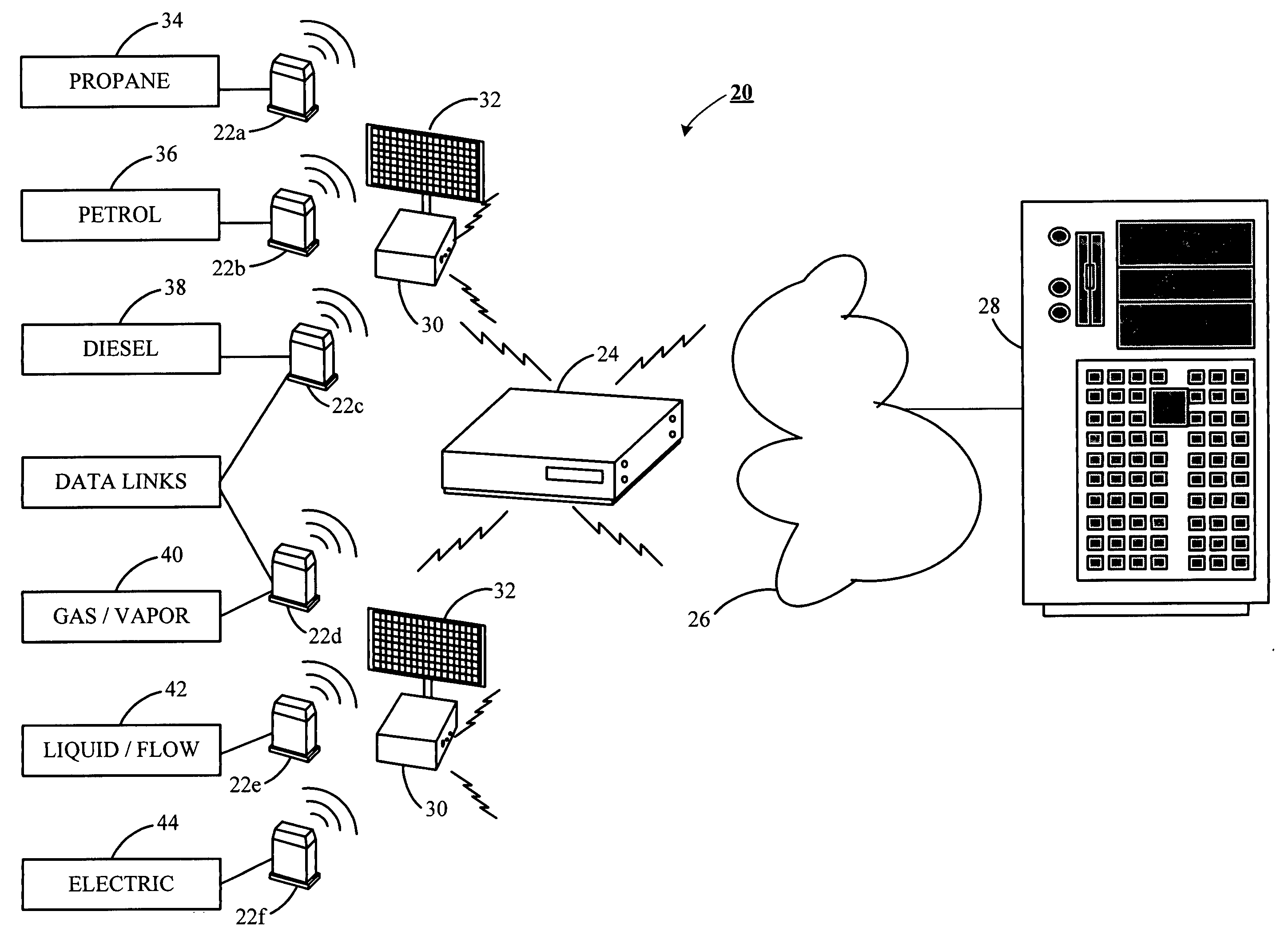
[0030]Referring now to the drawings, wherein like reference numerals indicate the same parts throughout the several views, a block diagram of the inventive monitoring and management system (“system”) 20 is shown in FIG. 1. System 20 is particularly useful for monitoring for leakage of a storage tank. In a typical system, one or more data links 22a-f (also referred to herein as an asset interface device), communicate with a data gate 24 (also referred to herein as a transmission device). The data gate 24, in turn, communicates via a pu...


PUM


Abstract

A system and method for remotely monitoring conditions at a location and for controlling devices at the location. The inventive system includes: a data link in communication with an electronically readable instrument, the data link having a transceiver configured for wireless digital communication; and a data gate having a wireless transceiver configured to communicate with one or more data links, the data gate also having an interface for connection to a communication network such as a land-line telephone network, cellular / pcs network, satellite communication network, or the like. In a preferred embodiment, the data gate communicates with a server via the communication network where the information from the electronically readable instrument is processed and made available to other devices over a computer network.

Description

RELATED APPLICATIONS[0001]This application claims priority to U.S. Provisional Application No. 60 / 537,379 filed Jan. 16, 2004, entitled System and Method for Remote Asset Monitoring.BACKGROUND OF THE INVENTION[0002]1. Field of the Invention[0003]The present invention relates to a system and method for the monitoring and management of data. More particularly, but not by way of limitation, the present invention relates to a system for remotely monitoring conditions at a storage tank, containment, dispenser sump, pipeline, or the like, in an intrinsically safe manner and for the management of data collected as a result of such monitoring.[0004]2. Background of the Invention[0005]Conditions such as the level of fluid in a storage tank, vapor / fluid flow through a pipeline, or electrical usage are often of concern. The need to remotely monitor such conditions has long been recognized. While electronically readable instrumentation may be readily available for such monitoring, there are few...

Claims


Application Information

Patent Timeline
Patent Type & Authority Patents(United States)
IPC IPC(8): G01F17/00G08B1/08G01F15/06G01F23/00G08C17/02
CPCG01F15/063G01F23/0069H04Q9/00G01F23/802
Inventor BOND, STUART K.FATE, JOSHUA R.GAUT, MICHAELSPENCER, TRAVIS J.ZANDBERGEN, JR., CORNELIS
Owner WORLDTELEMETRY
Why Eureka
Try Eureka