Air-permeable shoe

a shoe and air-permeable technology, applied in the field of air-permeable shoes, can solve the problems of inferior air permeability, insufficient and insufficient patents, and achieve the effect of efficient ventilation of the shoe interior

Inactive Publication Date: 2008-03-04
MORITA MIYATA
View PDF14 Cites 27 Cited by
  • Summary
  • Abstract
  • Description
  • Claims
  • Application Information

AI Technical Summary

Benefits of technology

[0005]In view of the above, it is an object of the present invention to provide an air-permeable shoe with higher air permeability by facilitating air inflow and outflow.
[0006]The present invention is configured such that a recess is formed on the sole upper surface, transverse grooves are formed on the recess bottom surface, the transverse grooves communicate with vent holes formed on the lateral surfaces of the sole, an elastic block body is fitted in the recess, the upper portions of the block body protrude above the sole upper surface, vertical holes are formed in the block body, on the recess bottom surface, a support sheet is provided so that when a load is applied, entry of the block body into the transverse grooves is prevented, the support sheet is air permeable, and the shoe interior and transverse grooves communicate with one another through the vertical holes and support sheet.
[0009]When a load is applied to the block body, the vertical holes deform, causing air to flow in and out between the vent holes and shoe interior. More specifically, during walking, a foot steps on the block body and separates therefrom. Because the block body protrudes above the sole, a load is intensively applied, thereby making a great change to the load applied to the block body. Because the block body is fitted in the recess, when a load is applied to the block body, the block body is not able to expand, causing the vertical holes to deform. The capacity of the vertical holes lowers, and air inside the vertical holes is pushed out. Air flows out from the vent holes through the support sheet and transverse grooves to the outside of the shoe. When the load applied to the block body decreases, the block body is restored to its original state, increasing the capacity of the vertical holes. At this time, air around the vertical holes is drawn in, causing air outside and inside of the shoe to flow in. Also, when a load is applied to the block body, the block body is pressed down and held by the support sheet. Therefore, the lower portions of the block body deform, preventing entry of the block body into the transverse grooves.
[0012]With the present invention, when the block body is stepped on during waking, the vertical holes greatly deform, causing air to flow in and out through the transverse grooves. As a result, air inside the shoe is discharged to the outside, and outside air flows in, thereby efficiently ventilating the shoe interior.

Problems solved by technology

With a constitution as in Laid-open Japanese Patent Application H3-236801, sufficient pumping action cannot be attained, so air inside the shoe is not discharged.
Thus, both patents are insufficient for ventilating the shoe interior, and have inferior air permeability.

Method used


Image

  • Air-permeable shoe
  • Air-permeable shoe
  • Air-permeable shoe

Examples


Embodiment Construction

:

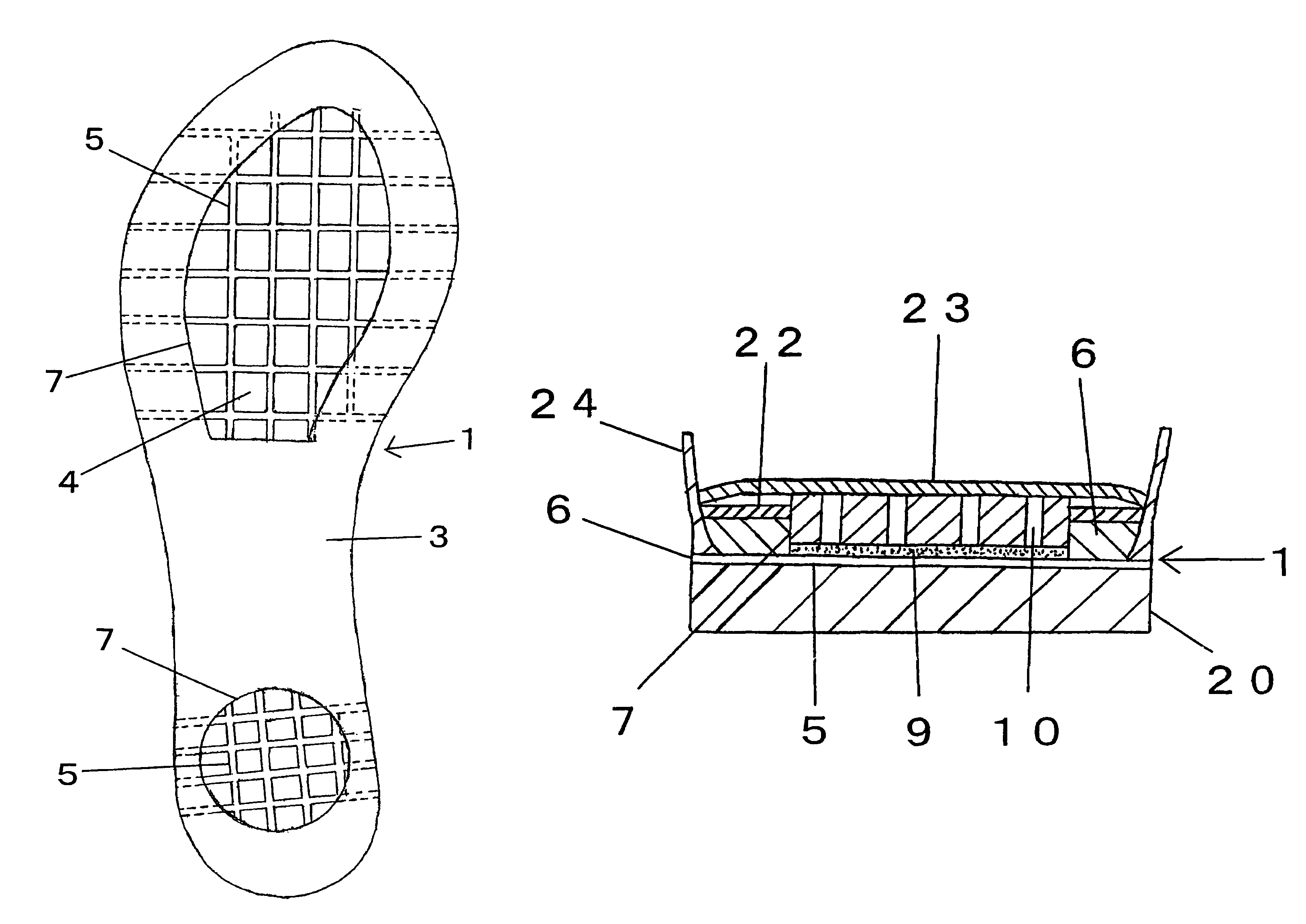
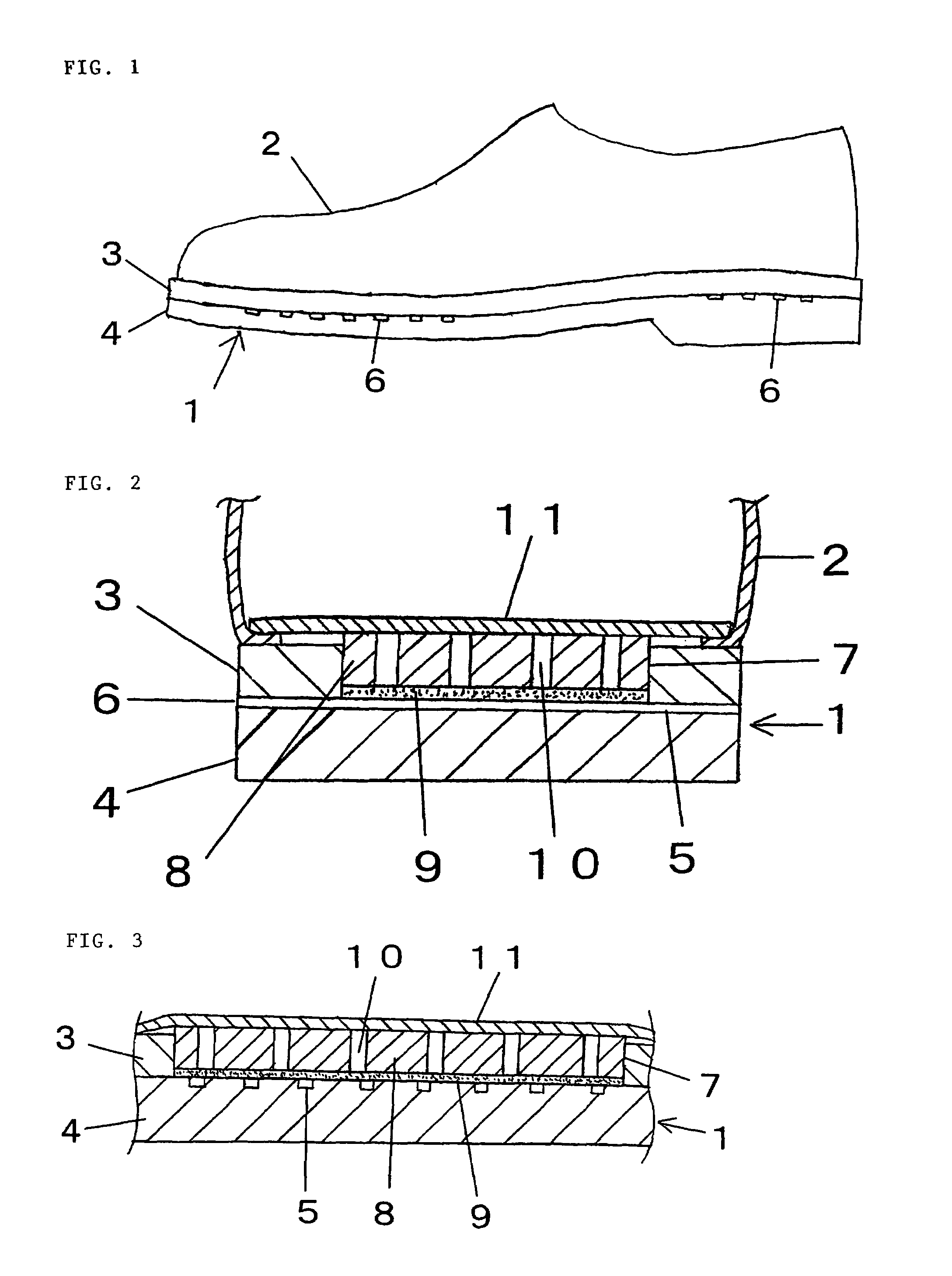
[0018]An air-permeable shoe of the present embodiment is shown in FIG. 1. The air-permeable shoe comprises a sole 1 and upper 2. As shown in FIGS. 2 and 3, the sole 1 has a two-layer structure comprising an upper sole 3 and lower sole 4. The upper sole 3 and lower sole 4, which are both made of rubber, are joined. The upper 2 is joined with an adhesive to or is sewn on the upper surface of the upper sole 3 so as to be integrally attached to the sole 1.

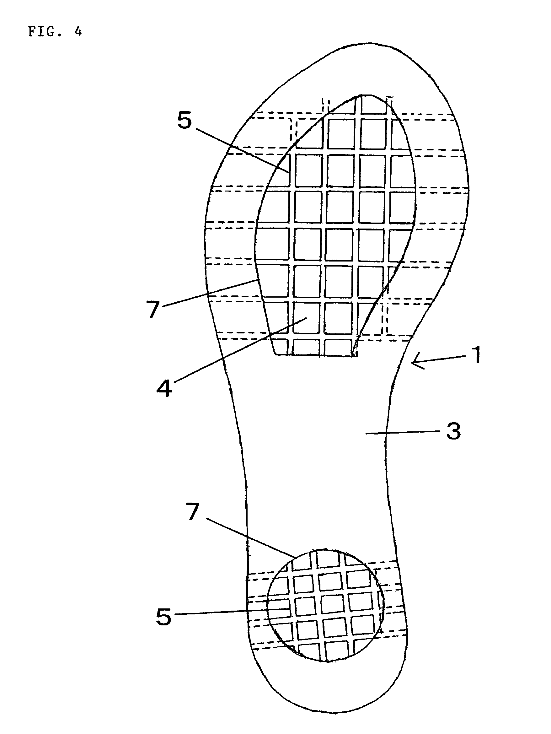
[0019]As shown in FIG. 4, transverse grooves 5 are provided on the upper surface of the lower sole 4. The transverse grooves 5 are formed in the front and back direction and right and left direction so that the transverse grooves 5 in the right and left direction intersect with the transverse grooves 5 in the front and back direction and the plurality of transverse grooves 5 communicate with one another. The transverse grooves 5 in the right and left direction reach the lateral surfaces of the lower sole 4, thereby forming, as shown i...


PUM


Abstract

On the upper surface of a lower sole transverse grooves reaching the lateral surface of the sole are formed, and an upper sole in which a recess is formed is stacked on the lower sole. In the recess, an elastic block body is fitted so that the upper portions of the block body protrude above the upper surface of the upper sole. On the upper surface of the lower sole, an air-permeable support sheet is disposed so as to support the block body in the recess. The shoe interior and tranverse grooves communicate with one another through the vertical holes in the block body and the support sheet, and when a load is applied to the block body, the vertical holes deform, causing air to flow in and out through the tranverse grooves.

Description

TECHNICAL FIELD[0001]The present invention relates to an air-permeable shoe with higher air permeability within the shoe.BACKGROUND OF THE INVENTION[0002]When a foot perspires, the shoe interior can grow humid. To prevent this, air permeability within a shoe can be improved. For example, a shoe of Laid-open Japanese Patent Application H3-236801 is configured such that a sole is made partly hollow to form a recess, vent grooves communicating from the recess to the lateral surfaces of the sole are formed, and air-permeable objects are accommodated in the recess. Humidity accumulated in the recess is discharged from the vent grooves by a pumping action induced during walking.[0003]Also, a shoe of Japanese Utility Model Registration No. 3080904 is configured such that on the sole upper surface, an elastic tube is provided, a conduit is connected to one end of the tube, and the conduit extends to the lateral surfaces of the sole. On the tube, vent holes are provided so that when the tube...

Claims


Application Information

Patent Timeline
Patent Type & Authority Patents(United States)
IPC IPC(8): A43B7/08
CPCA43B1/0045A43B7/08A43B7/125A43B7/088
Inventor MIYATA, YOSHIAKI
Owner MORITA MIYATA
Why Eureka
Try Eureka