Gripping device

a technology of a gripper and a grip handle, which is applied in the direction of article support devices, cycle equipment, manufacturing tools, etc., can solve the problems of not being able to securely or effectively hold any article, using that type of article, and both designs have certain limitations, so as to achieve the effect of improving the grip

Active Publication Date: 2008-03-04
POLARIS IND INC
View PDF37 Cites 55 Cited by
  • Summary
  • Abstract
  • Description
  • Claims
  • Application Information

AI Technical Summary

Benefits of technology

[0009]A gripping device in accordance with the present invention may also include a body selectably attached to a base. The base has a platform with a release. Actuating the release allows the body to be removed from the base.
[0010]A gripping device in accordance with the present invention may also provide for a gripping surface. The gripping surface has an engagement surface and a plurality of air pockets positioned below the engagement surface. Forcing the engagement surface against an article, or vice-versa, compacts the air pockets and provides for an improved grip.

Problems solved by technology

Both designs have certain limitations.
The first rack system may be able to securely hold one type of article, but it can only be used with that type of article.
The second rack system may be able to hold a variety of articles, but will not be able to securely or effectively hold any article.
However, the body itself has a predetermined configuration thus limiting the articles which it can securely hold.
While this device can accommodate a greater variety of articles than devices having a fixed body, this device cannot securely hold articles having round or oddly shaped cross sections in its gripping surface.

Method used


Image

  • Gripping device
  • Gripping device
  • Gripping device

Examples


Embodiment Construction

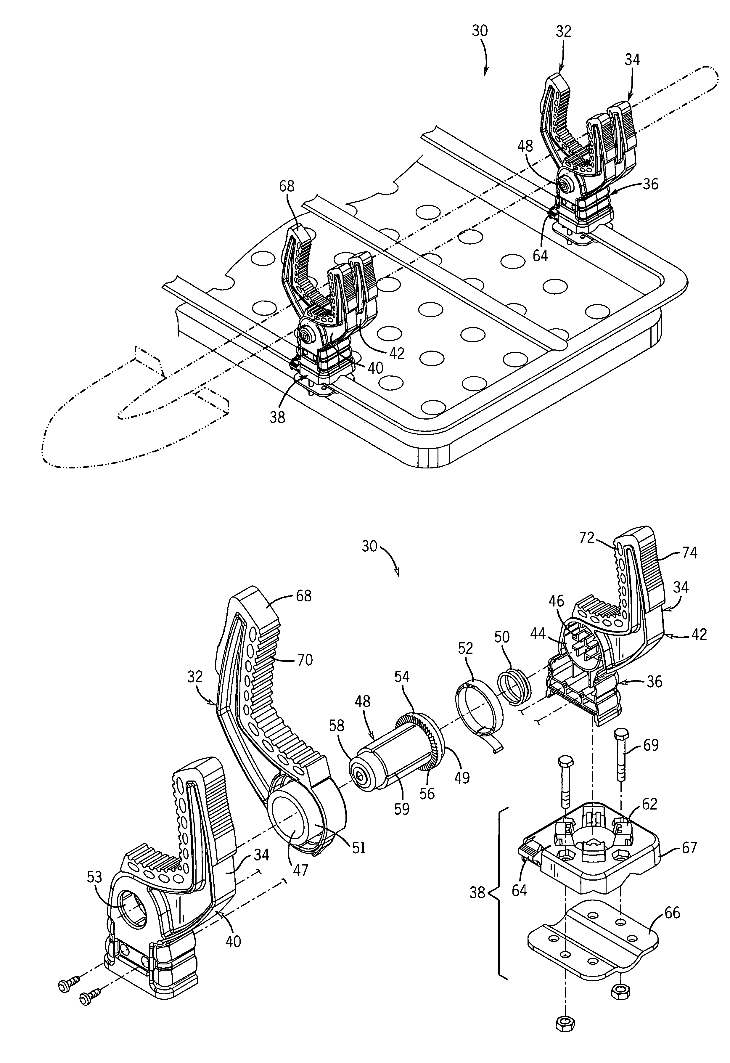
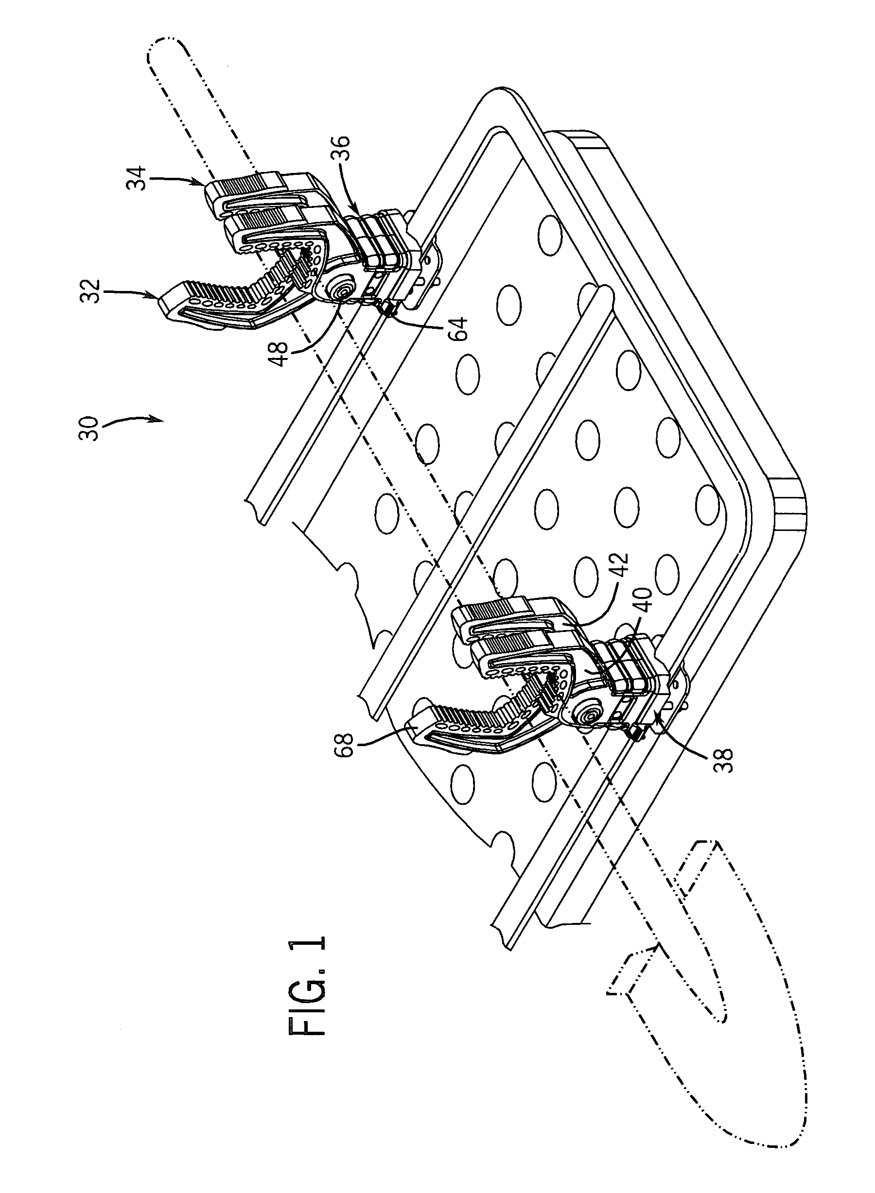
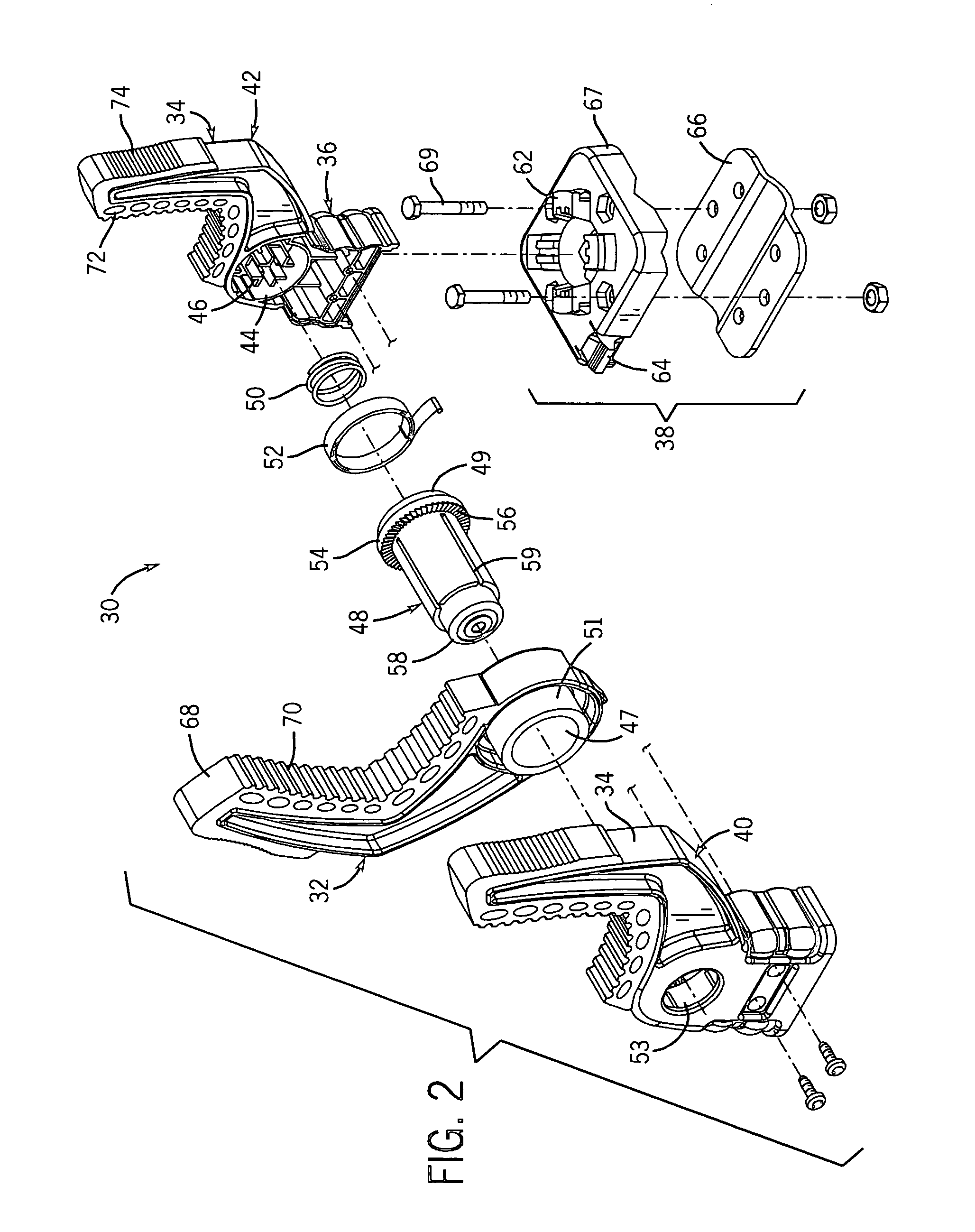
[0027]Illustrative embodiments of a gripping device (identified generally as 30) in accordance with the present invention are shown in FIGS. 1 through 15. While the invention may be susceptible to embodiment in different forms, there are shown in the drawings, and herein are described in detail, certain illustrative embodiments with the understanding that the present disclosure is to be considered an exemplification of the principles of the invention, and is not intended to limit the invention to those as illustrated and described herein. Additionally, features illustrated and described with respect to one embodiment could be used in connection with other embodiments.

[0028]A gripping device 30 has a plurality of arms 32, 34 attached to a body 36. At least one of the arms 32 is moveable with respect to the body 36, thereby allowing the gripping device 30 to securely hold different articles. The moveable arm 32 may be moved between a variety of positions, as shown in FIGS. 3 and 13. T...


PUM


Abstract

A gripping device having a body with at least one moveable arm. The moveable arm may be selectably positionable and secured at a position by a locking pin. The gripping device may have a body selectably attached to a base having a release. Actuating the release allows the body to be removed from the base. A gripping surface on an arm may have an engagement surface and a plurality of air pockets positioned below the engagement surface.

Description

BACKGROUND OF THE INVENTION[0001]This invention relates generally to a gripping device, and in particular, to a gripping device for use in connection with securing items to a vehicle.[0002]People have used various devices to grip and hold articles. Many of these devices are used to secure articles to a vehicle, such as a car, truck, or all-terrain vehicle (ATV). These devices allow articles to be securely attached to a vehicle while permitting the operator of the vehicle to focus on driving.[0003]Specifically, devices have been used to secure sporting equipment and tools to vehicles. Such devices include rifle racks and rack systems. These rack systems generally have a U-shaped body. The equipment is placed into the U-shaped body. The body, however, generally has a predetermined shape. The shape may be configured so as to securely hold a specific article such as a rifle. Alternatively, the shape may be configured so as to hold many different types of articles. Both designs have cert...

Claims


Application Information

Patent Timeline
Patent Type & Authority Patents(United States)
IPC IPC(8): B62J7/00B60R11/00B62J9/00B25B5/04B25B5/16B60R9/00F16B2/10
CPCF16B2/10
Inventor ALLING, JONPELLAND, MIKEAPER, GREGDOORHY, BRENDAN
Owner POLARIS IND INC
Why Eureka
Try Eureka