Elevator installation with information representation on a shaft door

a technology of information representation and elevator shaft, which is applied in the field of elevator shaft, can solve the problems of complex design, complex structure, and inability to have elevators in modern buildings,

Active Publication Date: 2008-03-04
INVENTIO AG
View PDF4 Cites 8 Cited by
  • Summary
  • Abstract
  • Description
  • Claims
  • Application Information

AI Technical Summary

Benefits of technology

[0006]Against the above-discussed background, an object of the present invention is an elevator installation for and a method for representation of information on shaft doors of the elevator installation in which the representation of information is made possible without impairing the design of elevator lobbies and nevertheless achieving a qualitatively high-grade representation of information.
[0008]In a modern office building glass or a similar material which is at least partly transparent is frequently used for shaft doors. This characteristic is advantageously utilized in the case of the elevator installation according to the present invention. By virtue of the projection from the elevator shaft it is no longer necessary to arrange a projector and deflecting devices in the elevator lobby. Darkened light conditions prevail in most elevator shafts so that projection from the elevator shaft onto a shaft door can take place with a high quality. A further advantage results from the fact that nobody can enter the beam path of the projector. Thus, darkening of the represented information is prevented.
[0009]In one advantageous embodiment of the present invention there is incorporated in the shaft door a material which enables representation of an image on a side of the shaft door oriented towards the elevator lobby. For example, it is possible to incorporate in shaft doors, which consist of glass, a film which produces a partial reflection of the light beams back into the elevator shaft, wherein an image is imaged, by this incomplete reflection, on the side of the shaft door oriented towards the elevator space. This has the advantage that a person waiting in the elevator lobby is not dazzled by the light radiated by the projector. Moreover, an improvement in the contrast of the represented image is possible by the arrangement of the film in the glazed shaft doors.
[0012]In the case of use of the above-mentioned deflecting devices the arrangement of the projector at a shaft door wall or at left-hand or right-hand walls in the elevator shaft is made possible. Almost any free space in the elevator shaft can thereby be utilized in order to mount the projector in a space-saving and unobtrusive manner.
[0016]It is advantageous if the sensors that detect a position of the elevator car are arranged in the elevator shaft and the projection of the image can be switched off or switched on in dependence on the elevator car position. It is made possible by these sensors to stop the projection at the respective floor when an elevator car arrives. After the elevator car has again freed the shaft door, the projection is continued.
[0017]In an advantageous embodiment of the present invention the projector is arranged within the shaft door wall, wherein the image is projected in the elevator shaft to the deflecting devices arranged there. The deflecting devices deflect the light beams to the respective shaft door. The arrangement of the projector and the shaft door wall makes it possible for the projector to be accessible from an elevator lobby. Thus, the projector can, for example, be maintained or adjusted independently of the operation of the elevator installation. This has the advantage that the service provider responsible for the projectors does not have to be familiar with the specifics of the elevator control, since otherwise the projectors could only be maintained and operated by the elevator service providers.

Problems solved by technology

The absence of elevators from modern buildings is no longer imaginable.
Modern buildings are subject to a complicated architectonic design.
A mounting of that kind in the elevator lobby does, however, have a disadvantageous effect on the design, which is complicated in its nature, of modern office buildings, since the projector has to be suspended from a ceiling and deflecting devices for projection of an image have to be positioned.
Moreover, elevator lobbies in modern office buildings are exposed to normal light conditions.
Even high-quality and expensive projectors cannot actually project a qualitatively high-grade image in normal daylight.
A further problem in the installation of projectors in elevator lobbies is that the projector has to be arranged at a substantial distance from the shaft door in order to be able to represent an image or video over a large area.
This has the consequence that a person entering the beam path of the projector darkens the image to be represented.
This darkening can be avoided only partly by complicated constructions of image deflecting devices, wherein these constructions can spoil the architectonic design of the elevator lobby.

Method used


Image

  • Elevator installation with information representation on a shaft door
  • Elevator installation with information representation on a shaft door
  • Elevator installation with information representation on a shaft door

Examples


Embodiment Construction

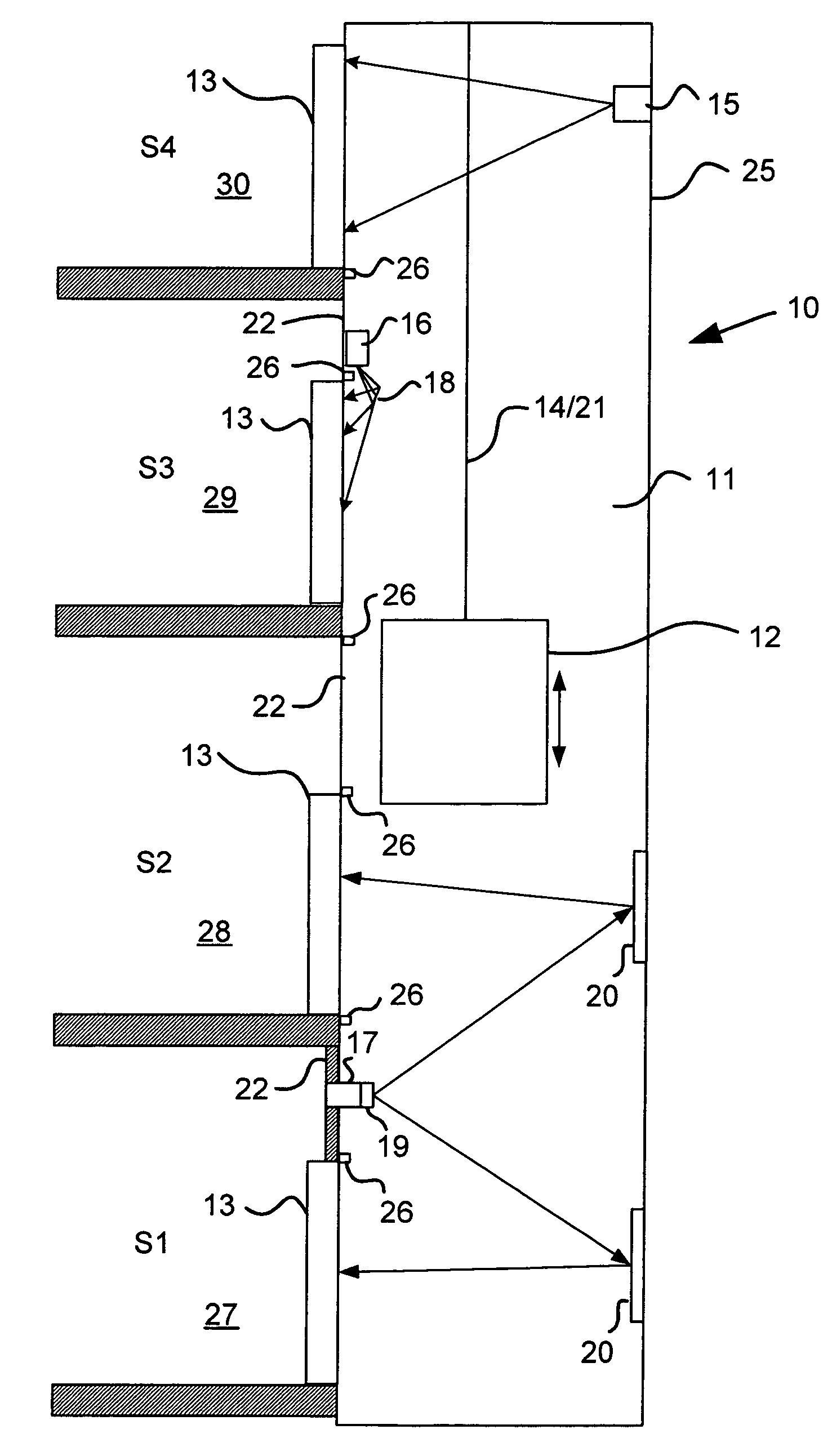
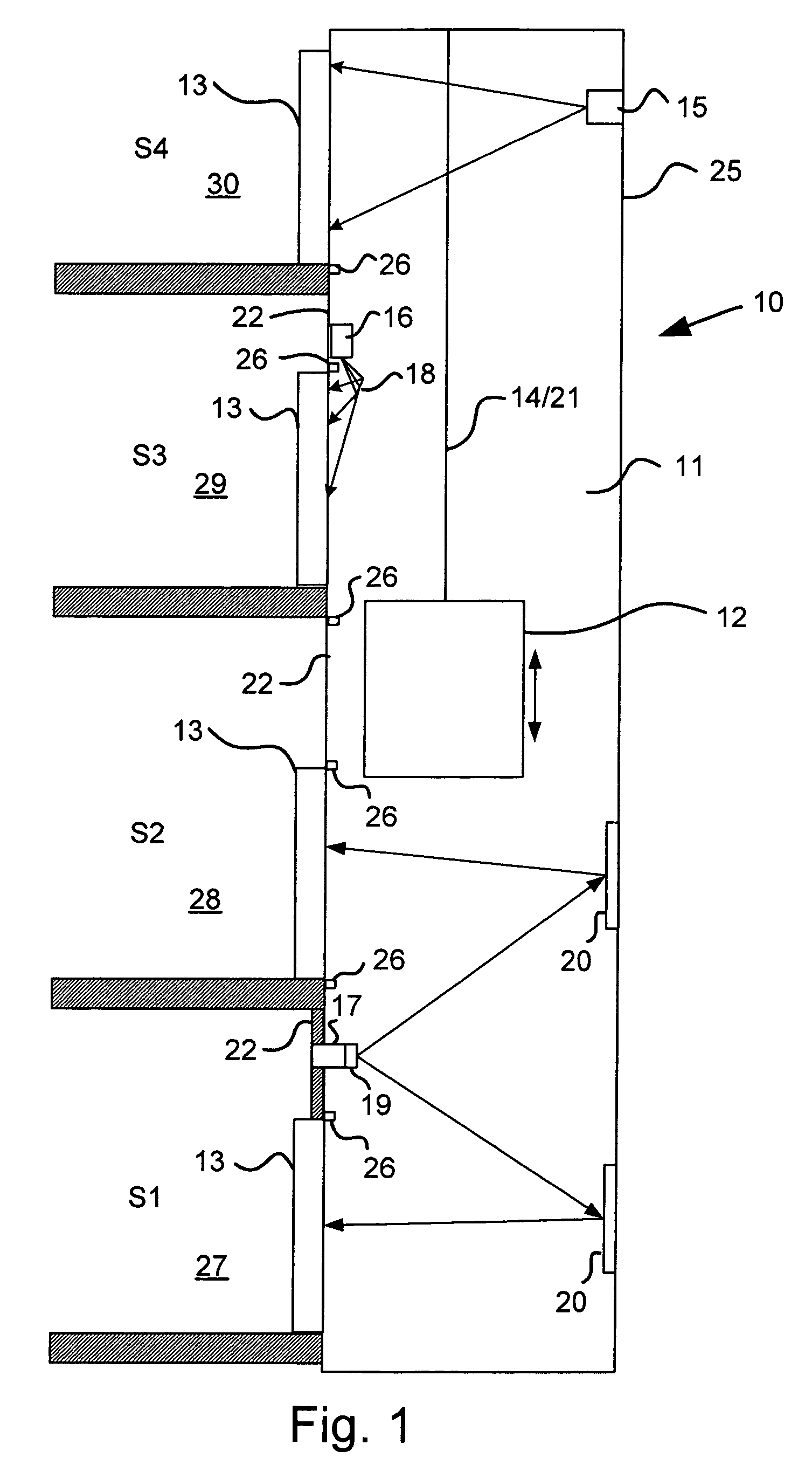
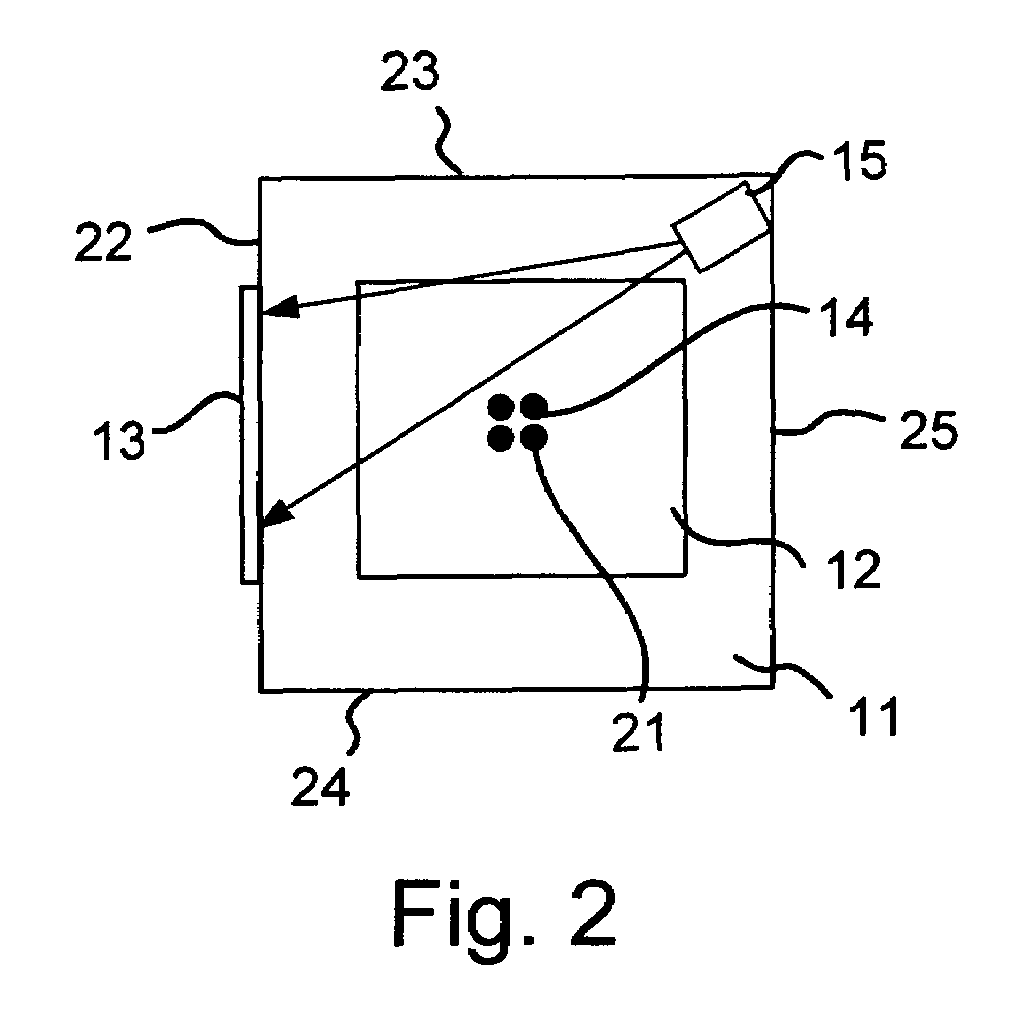
[0024]The construction of an elevator installation 10 according to the present invention is explained with reference to FIG. 1. The elevator installation 10 comprises an elevator shaft 11 in which an elevator car 12 is moved between floors S1, S2, S3 and S4. The elevator car 12 is fastened to an elevator cable 14 and is moved by a motor (not illustrated) between the individual floors S1 to S4. The elevator car 12 is connected by a suspended cable 21 with a control unit (not illustrated). The elevator shaft 11 is closed by respective shaft doors 13 at the floors S1 to S4. Elevator lobbies 27, 28, 29 and 30 are disposed in front of the shaft doors 13 in the respective floors S1 to S4. The elevator shaft 11 has a shaft door wall 22 which delimits the elevator shaft 11 from the elevator lobbies 27 to 30. As illustrated in FIG. 2, left-hand and right-hand walls of the elevator shaft 11 are denoted by the reference numerals 23 and 24 respectively. The elevator shaft wall opposite the shaf...


PUM

PropertyMeasurementUnit
transparentaaaaaaaaaa
distanceaaaaaaaaaa
areaaaaaaaaaaa

Abstract

An elevator installation includes an elevator car moved in an elevator shaft between floors in a building. A shaft door for closing the elevator shaft is arranged at each floor. A method for representing information on the shaft doors makes possible a qualitatively high-grade projection of an image on the shaft door. The shaft doors are formed to be at least partly transparent, wherein a projector is arranged in the elevator shaft and projects an image onto the side of the shaft door facing the elevator shaft.

Description

BACKGROUND OF THE INVENTION[0001]The present invention relates to an elevator shaft with an elevator car arranged to be movable in the elevator shaft between floors, wherein a shaft door for closing the elevator shaft is arranged on at least one floor. In addition, the present invention relates to a method for representing information on a shaft door of an elevator installation.[0002]In order to bridge over the waiting time for an elevator car the passengers in the vicinity of the elevator installation are frequently shown information in the form of images or videos. These images can relate to the operation or status of the elevator installation or, however, simply contain advertising messages. An elevator installation is shown in European Patent EP 1 069 065 A1 in which a projector is arranged in an elevator lobby and projects an image onto a shaft door of an elevator installation or onto a car door of an elevator car.[0003]The absence of elevators from modern buildings is no longe...

Claims


Application Information

Patent Timeline
Patent Type & Authority Patents(United States)
IPC IPC(8): G03B21/00G02F1/1335G03B21/28G03B21/56G09F7/00H04N5/64H04N9/31B66B1/34
CPCB66B13/24B66B19/007
Inventor SVENSSON-HILFORD, LENNARTFRIEDLI, PAUL
Owner INVENTIO AG
Why Eureka
Try Eureka