
Continuously variable transmission or clutch with ortho-planar compliant mechanism

a technology of orthoplanar springs and transmission mechanisms, applied in mechanical devices, ring springs, hoisting equipment, etc., can solve the problems of back plate, large space to accommodate the minimum depth of the spring, and difficulty in tuning for different operating conditions, so as to reduce weight, facilitate and reduce manufacturing costs, and less space

Inactive Publication Date: 2008-03-04
BRIGHAM YOUNG UNIV
View PDF29 Cites 24 Cited by
  • Summary
  • Abstract
  • Description
  • Claims
  • Application Information

AI Technical Summary

Benefits of technology

[0007]It has been recognized that it would be advantageous to develop a transmission or clutch that requires less space, decreases weight, is easier and less expensive to manufacture, reduces rotation, and reduces friction, wear and noise. In addition, it has been recognized that it would be advantageous to develop a transmission or clutch that is easier to tune.

Problems solved by technology

One disadvantage with helical compression springs is that they have only a single spring constant, making it difficult to tune for different operating conditions.
Another disadvantage with helical compression springs is that they require relatively large space to accommodate the spring's minimum depth.
Another disadvantage with helical compression springs is that they require a back plate to provide the spring reaction force on the pulley sheaves.
Another disadvantage with helical compression springs is that some rotation or twisting occurs during their operation, thereby increasing friction, wear and noise.

Method used


Image

  • Continuously variable transmission or clutch with ortho-planar compliant mechanism
  • Continuously variable transmission or clutch with ortho-planar compliant mechanism
  • Continuously variable transmission or clutch with ortho-planar compliant mechanism

Examples


Embodiment Construction

[0024]Reference will now be made to the exemplary embodiments illustrated in the drawings, and specific language will be used herein to describe the same. It will nevertheless be understood that no limitation of the scope of the invention is thereby intended. Alterations and further modifications of the inventive features illustrated herein, and additional applications of the principles of the inventions as illustrated herein, which would occur to one skilled in the relevant art and having possession of this disclosure, are to be considered within the scope of the invention.

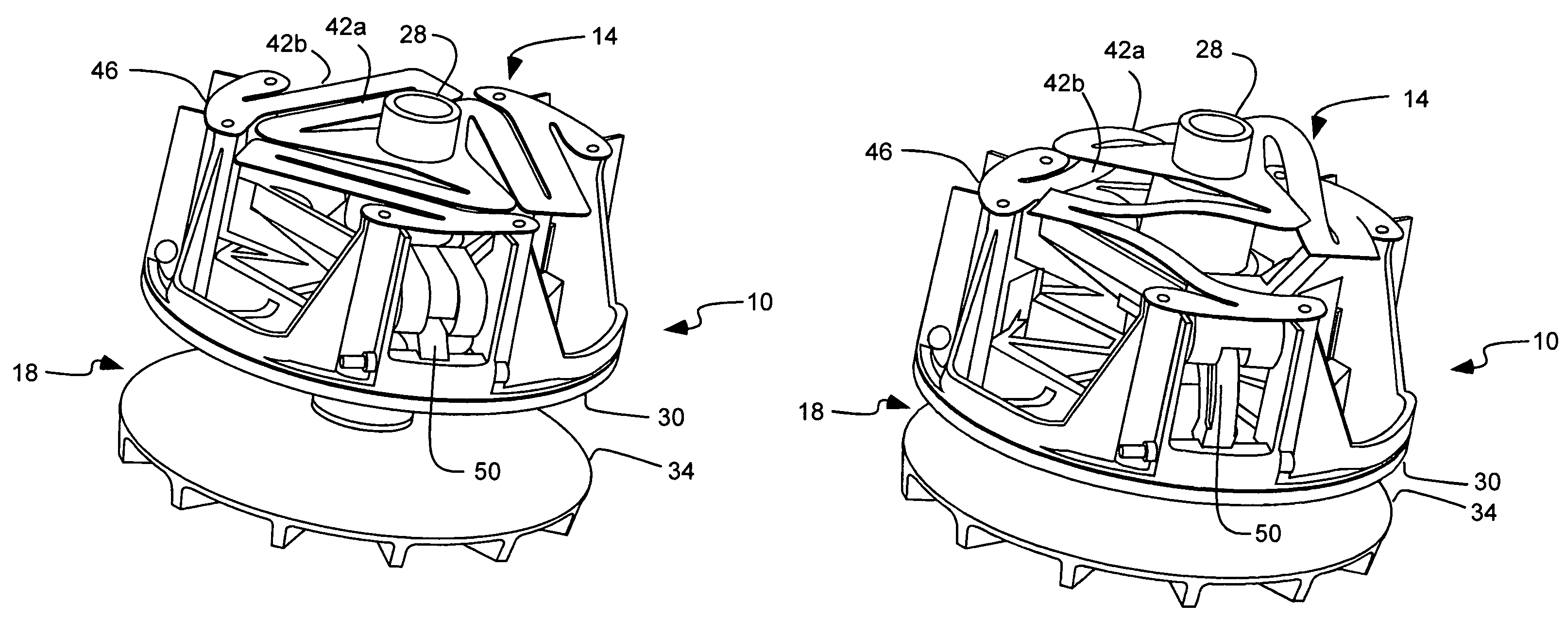
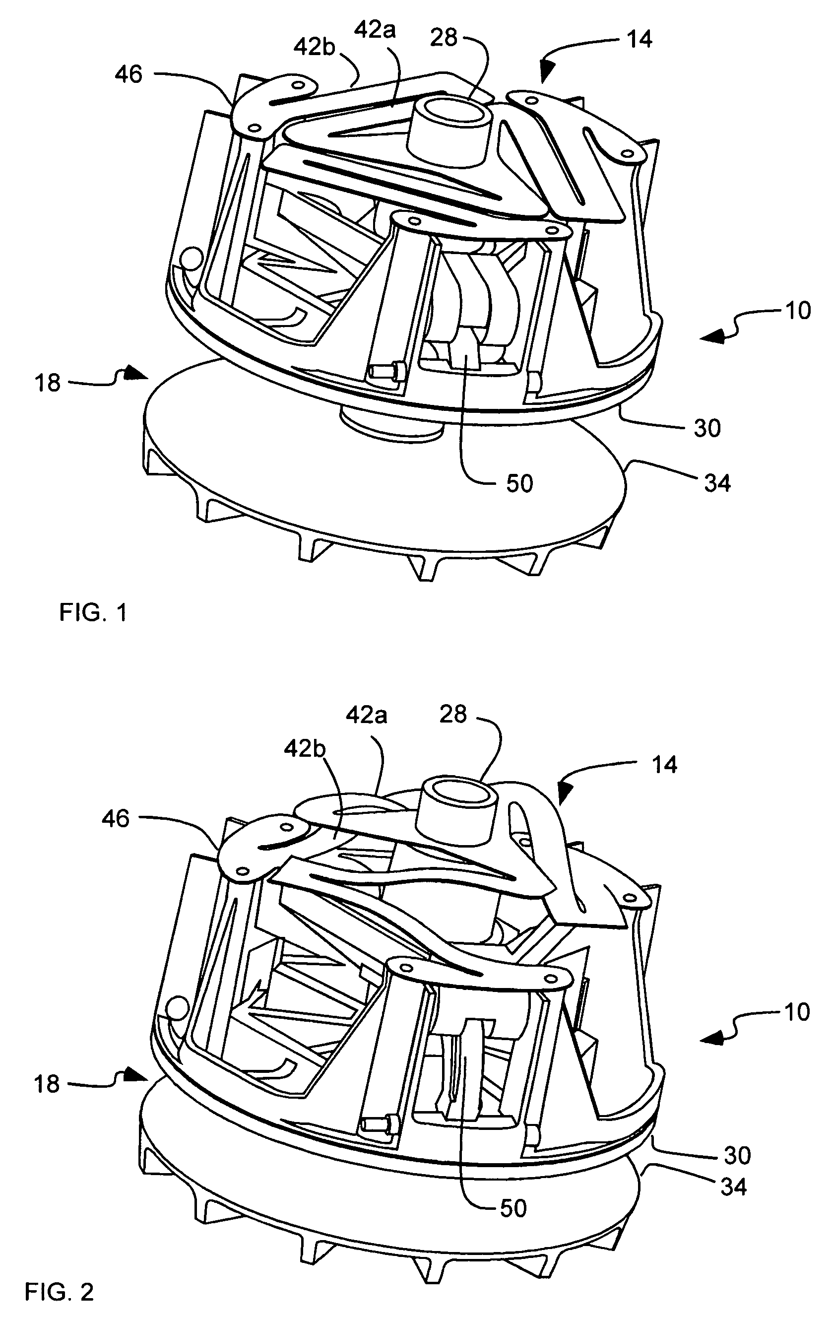
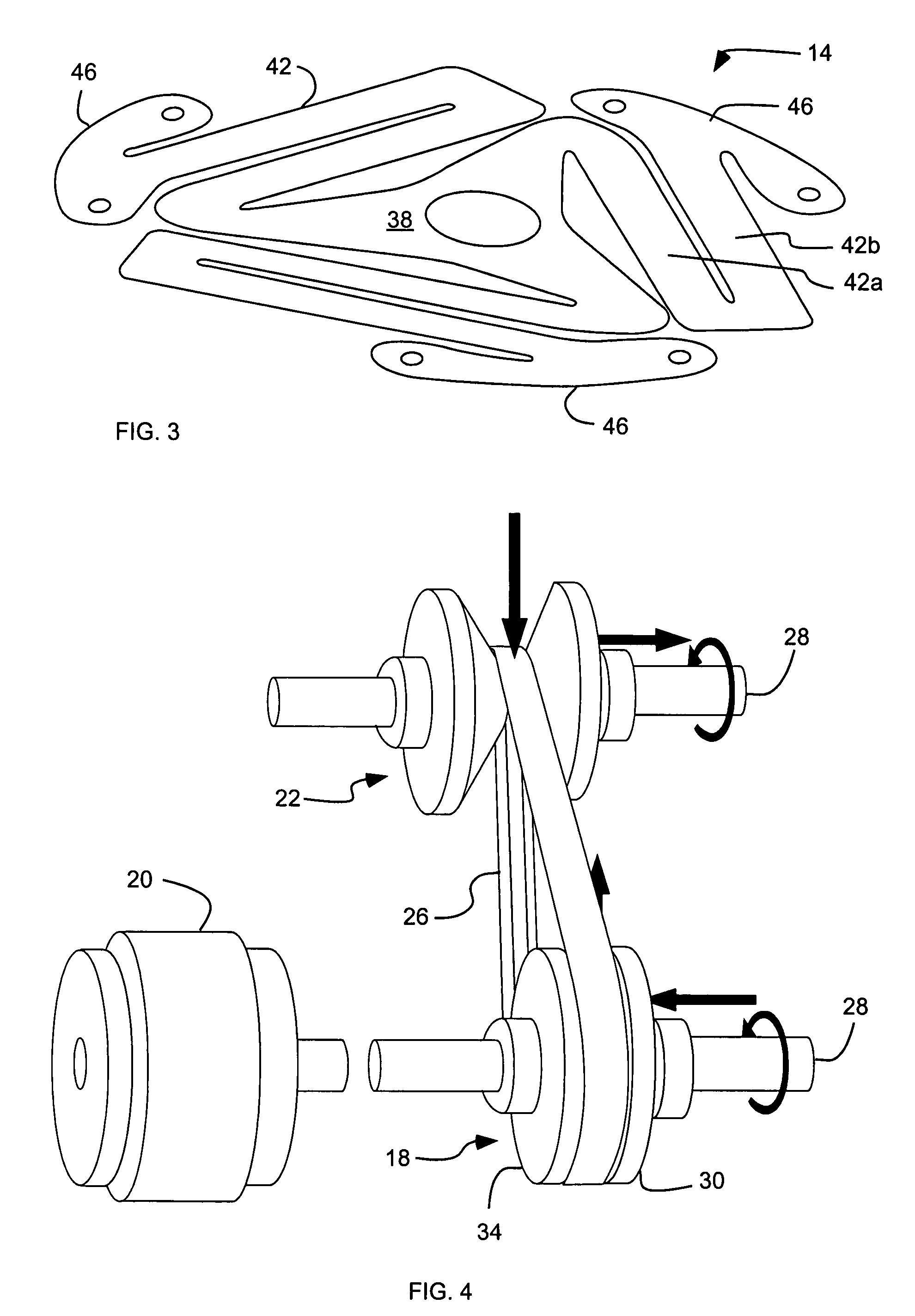
[0025]As illustrated in FIGS. 1-7b, a continuously or constant variable transmission or clutch (or portion thereof), indicated generally at 10, is shown with a ortho-planar compliant mechanism, indicated generally at 14, in accordance with the present invention for providing power transmission between a power source, such as a gas engine or motor, and a driven member, such as an axle for a wheel or track. Such a ...


PUM


Abstract

A continuously variable transmission or clutch device (10) includes at least one pulley (18) rotatable on a pivot (28) and having a pair of adjustable sheaves (30, 34) including a movable sheave (30) movable along the pivot. An ortho-planar compliant mechanism (14) is capable of elastic deformation and operatively coupled to the movable sheave to bias the movable sheave towards or away from the other sheave. The ortho-planar compliant mechanism includes a substantially flat configuration and is deflectable therefrom as the movable sheave moves. The ortho-planar compliant mechanism can include a center platform (38) disposed on the pivot and a plurality of arms (42) extending from the platform to distal ends (46) coupled to the movable sheave.

Description

[0001]Priority is claimed of U.S. Provisional Patent Application No. 60 / 470,602, filed May 14, 2003, entitled “Continuously Variable Transmission or Clutch with Ortho-Planar Compliant Mechanism”; and this application is a continuation-in-part of U.S. patent application Ser. No. 10 / 258,568 U.S. Pat. No. 6,983,924, filed Jun. 30, 2003, entitled “Compliant, Ortho-Planar, Linear Motion Spring,” which was the National Stage of International Application No. PCT / US01 / 13351, filed Apr. 25, 2001, which claims the benefit of U.S. Provisional Patent Application No. 60 / 199,905, filed Apr. 26, 2000.BACKGROUND OF THE INVENTION[0002]1. Field of the Invention[0003]The present invention relates generally to a continuously or constant variable transmission (CVT) or clutch, and ortho-planar springs or compliant mechanisms.[0004]2. Related Art[0005]Some vehicles, such as snowmobiles and all-terrain vehicles (ATVs) utilize a transmission or clutch that is continuously or constantly variable. Such contin...

Claims


Application Information

Patent Timeline
Patent Type & Authority Patents(United States)
IPC IPC(8): F16H55/56F16F1/34F16H55/36F16F1/32F16F3/02F16F15/073
CPCF16F1/324F16F3/026F16F15/073F16F2236/027
Inventor WHITING, MICHAEL J.HOWELL, LARRY L.TODD, ROBERT H.MAGLEBY, SPENCER P.ANDERSON, MARK C.RASMUSSEN, NATHAN O.
Owner BRIGHAM YOUNG UNIV
Learn More