Pyrolysis

Inactive Publication Date: 2008-03-04
SHELL OIL CO
View PDF2 Cites 4 Cited by
  • Summary
  • Abstract
  • Description
  • Claims
  • Application Information

AI Technical Summary

Benefits of technology

[0008]The present invention relates to a process which makes it possible to pyrolize light feed in a furnace designed for pyrolyzing heavy feed, more specifically to pyrolize gaseous

Problems solved by technology

It is well known that coke deposits in the cracking zone during operation.
As there is generally not sufficient spare capacity for pyrolyzing gaseous feed, the gaseous feed generally is sent to a pyrolysis unit designed for pyrolyzing liquid feed.
However, only a relatively small amount of gaseous feed can be sent to a furnace designed for liquid feed.
The narrower, longer tubes in the convection zone designed for liquid feed, cause a larger pressure drop.
Further, it is disadvantageous to process gaseous

Method used


Image

  • Pyrolysis
  • Pyrolysis

Examples


Embodiment Construction

[0015]It is to be understood that the scope of the invention may include any number and types of process steps between each described process step or between a described source and destination within a process step.

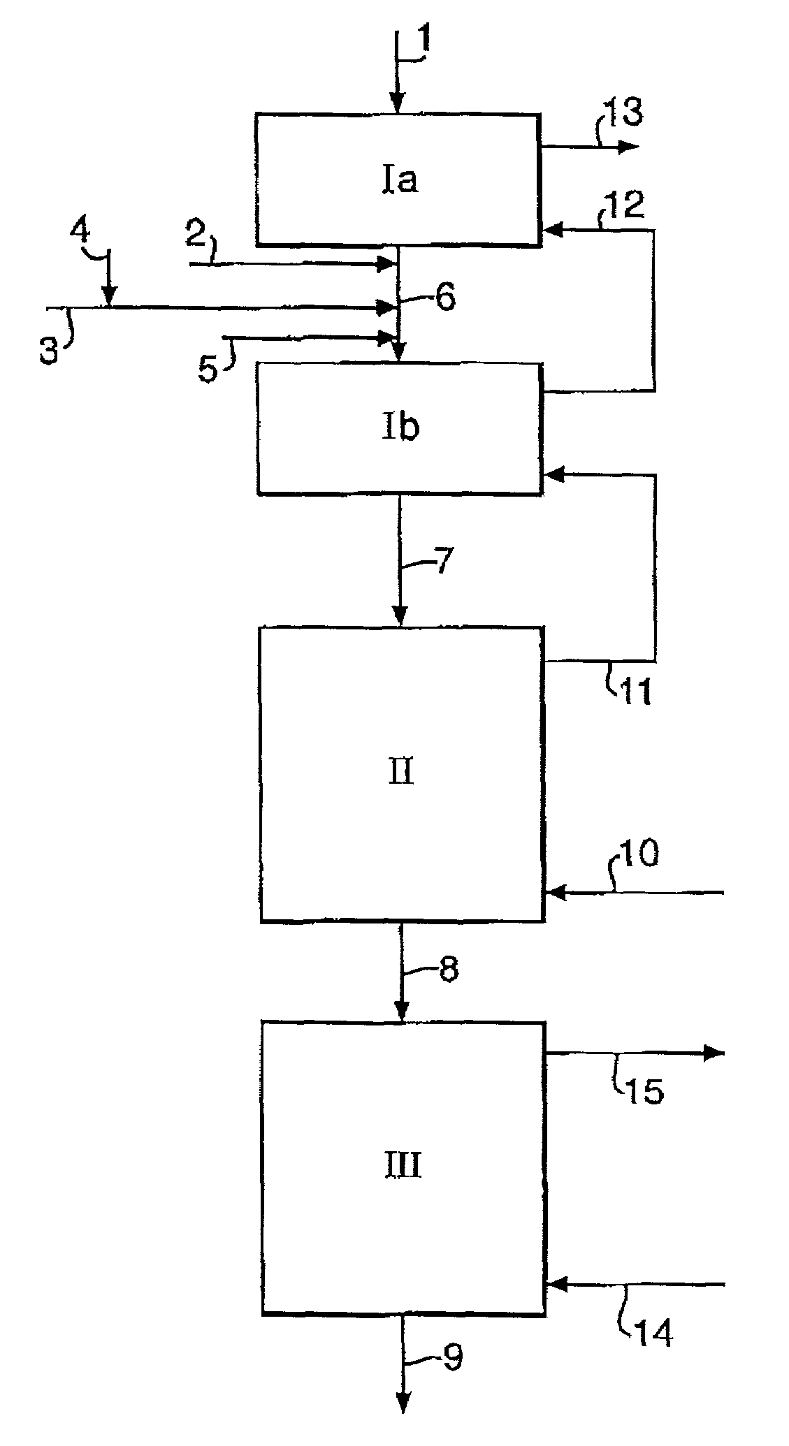
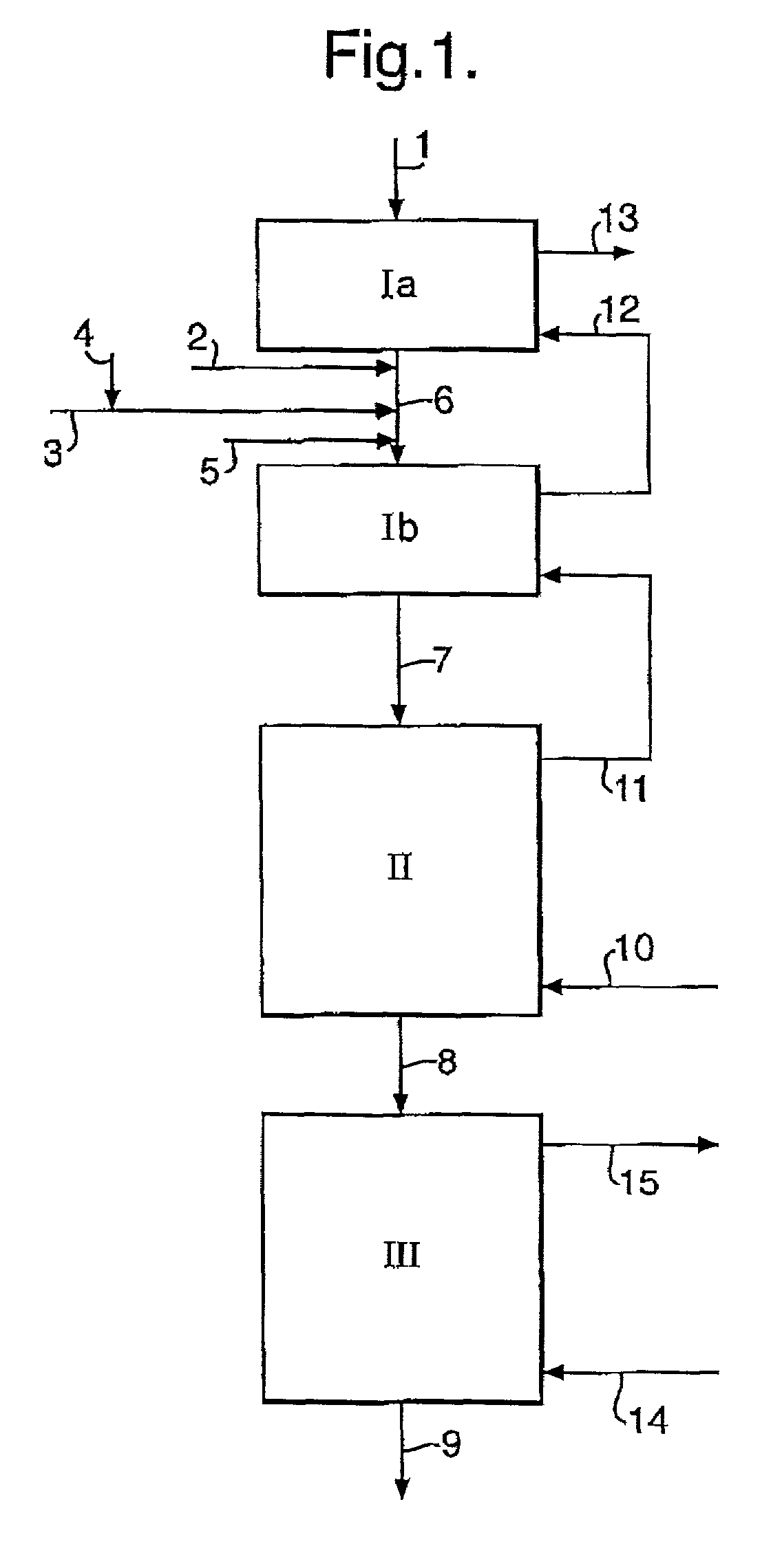
[0016]The light feed is pyrolyzed in a pyrolysis furnace designed for pyrolyzing heavy feed by a process comprising:[0017](1) heating the feed in a convection zone,[0018](2) further heating the product of the convection zone in a cracking zone where the feed is converted into lower boiling products,[0019](3) cooling the product of the cracking zone, and[0020](4) separating the cooled product into desired end-products, in which process light feed is introduced at the feed inlet of the convection zone and further light feed is introduced into the convection zone together with dilution gas.

[0021]Usually and preferably, all product of a process step will be subjected to the next process step. However, it is possible to send only part of the product of a process step to the ne...


PUM

PropertyMeasurementUnit
Weight ratioaaaaaaaaaa
Lightaaaaaaaaaa

Abstract

Process for pyrolyzing a light feed in a pyrolysis furnace designed for pyrolyzing heavy feed, in which process part of the light feed is introduced at the feed inlet of the convection zone of the pyrolysis furnace and further light feed is introduced into the convection zone together with the dilution gas.

Description

[0001]The invention pertains to a process for pyrolyzing a light feed.BACKGROUND OF THE INVENTION[0002]The production of olefins, in particular ethene, is in general achieved by pyrolyzing petroleum hydrocarbon feedstocks such as gas oil obtained from an atmospheric distillation column, naphtha, natural gas liquids, butane, propane or ethane. Some crackers can use even heavier feedstocks, such as gas oil obtained from a vacuum distillation column.[0003]Pyrolysis is also called steam cracking and comprises thermal cracking of hydrocarbons in the presence of dilution gas. The process comprises a convection zone, a cracking zone, a cooling zone and a separation zone. The pyrolysis furnace comprises the convection zone and the cracking zone. The convection zone comprises a first preheating zone and a second preheating zone. Generally, feed is heated in the first preheating zone, and dilution gas is added to the feed before the mixture of feed and dilution gas is sent to the second prehe...

Claims


Application Information

Patent Timeline
IPC IPC(8): C07C4/04C10G9/00C07C5/333C07C11/04
CPCC07C4/04
Inventor CRUIJSBERG, EMIL EDUARD ANTONIUSGOOSSENS, JEROEN CORNELIS JOSEPHUS MARIAVAN WESTRENEN, JEROEN
Owner SHELL OIL CO
Why Eureka
Try Eureka