Confocal microscope

a confocal microscope and microscope technology, applied in the field of microscopes, can solve the problems of difficult adjustment of pinhole diameter, difficult setting of optimum confocal pinhole diameter within the objective lens, and difficulty in adjusting and centering a plurality of pinholes and lens arrays, and achieve the effect of high speed

Inactive Publication Date: 2008-03-04
OLYMPUS CORP
View PDF8 Cites 88 Cited by
  • Summary
  • Abstract
  • Description
  • Claims
  • Application Information

AI Technical Summary

Benefits of technology

[0029]Furthermore, by the scanning of the illumination light using a galvanometer mirror and the illumination of the sample body by the timed shifting of a single-point illumination light temporally employing a mirror or diaphragm of a size that achieves the resolution limit of the light modulation member in which the shade pattern is alterable, a confocal aperture effect can be generated in both the X and Y directions of the image.
[0030]Furthermore, where scanning of the samp...

Problems solved by technology

Although hitherto disclosed microscopes include a disk scanner microscope (U.S. Pat. No. 5,717,519) in which the process of tandem scanning is improved and in which, for example, a lens array is employed, using this method, the alteration of the pinhole diameter is difficult and the setting of the optimum confocal pinhole diameter within the objective lens is very difficult.
Additionally, in this method, the adjustment and centering of a plurality of pinholes and lens array is technically difficult.
In addition, although, for a sample body in which there is extensive scattering, single-point scanning of the sample body can improve the contrast of the image, the process of changeover from multiple-point scanning to single-point scanning is very difficult.
In addition, although a method for producing an image by the scanning of an array comprising a plurality of focal points in a small range and a method for producing an image in which a plurality of linear laser beams are scanned over a small range have been disclosed (U.S. Pat. No. 6,028,306), using these methods, the adjustment and centering of a plurality of pinholes and lens array is technically difficult.
In addition, although, for a sample body in which there is extensive scattering, single-point scanning of the sample body can raise the contrast of the image, the process of changeover from multiple-point scanning to single-point scanning is very difficult.
In addition, the implementation of line sequence scanning in which the scanning excitation wavelength is altered for each wavelength is very difficult.
In addition, the magnification cannot be altered easily without the employment of a relay system and, furthermore, the setting of the optimum scanning speed for the sample body is difficult.
In addition, b...

Method used


Image

  • Confocal microscope
  • Confocal microscope
  • Confocal microscope

Examples


Embodiment Construction

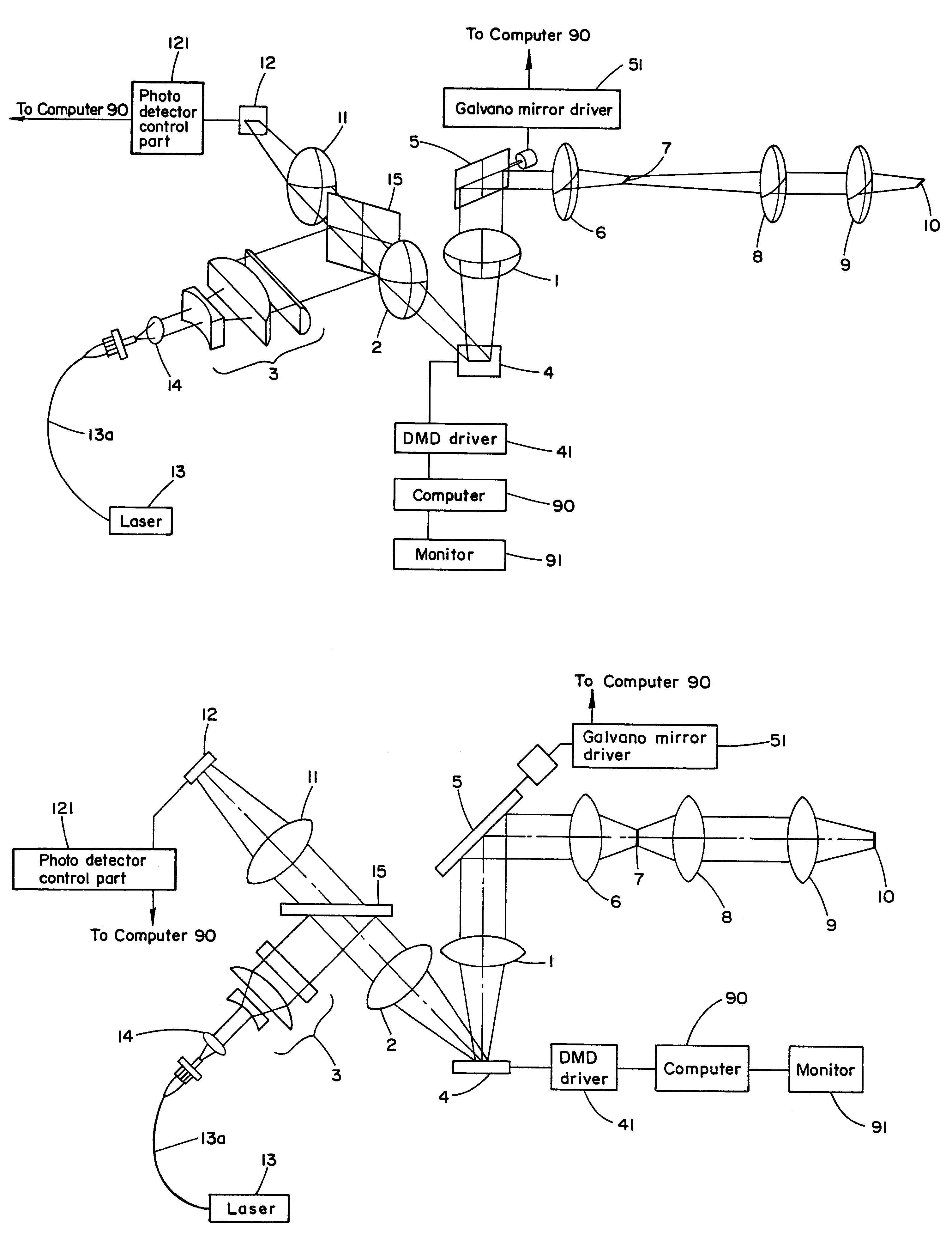
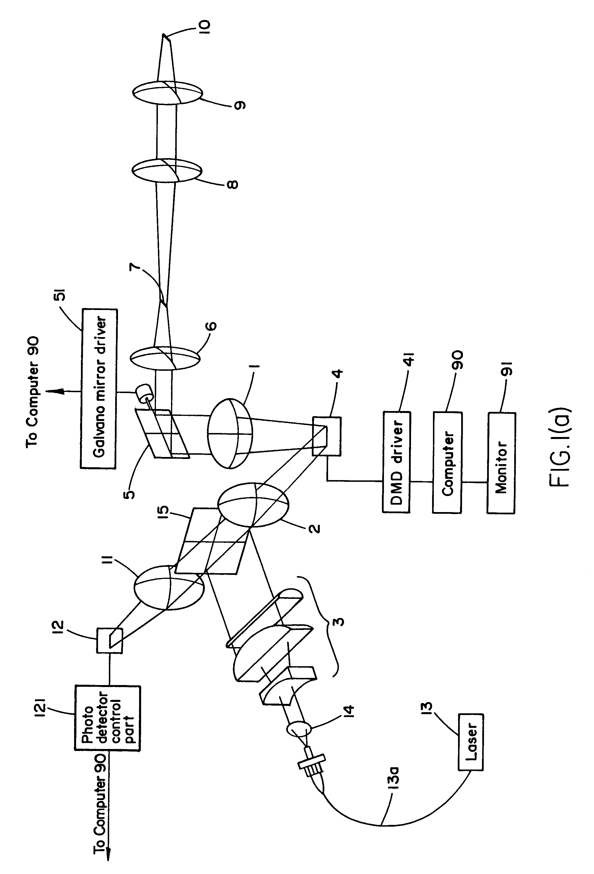
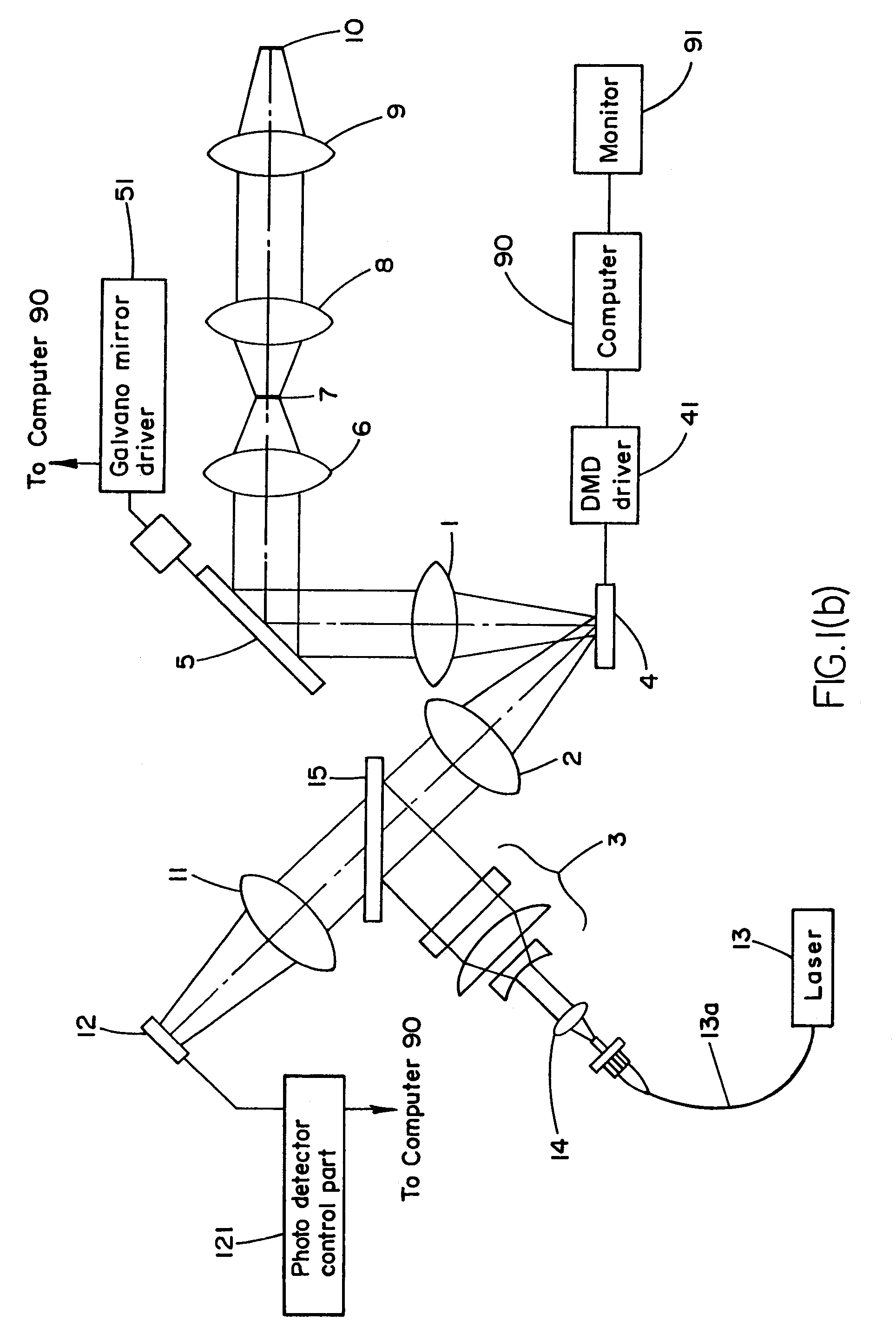
[0062]Referring now to FIGS. 1(a) and 1(b), a description is given of a first embodiment of an optical system of the present invention. FIG. 1(a) represents a diagonal view of the optical system of the first embodiment, and FIG. 1(b) represents the view thereof from above. The illumination in the configuration of the device of the present invention is implemented by the employment of a laser 13. If a continuous wave laser is employed the light can be introduced into the device by way of a single mode fiber 13a. The introduced light is formed as a parallel light beam by a collimator lens 14. If a laser for implementing an ultra short pulse light, by way of example, of a femto-second, is employed, the light can be introduced by the employment of a hollow optical fiber 13a. If the employment of a hollow optical fiber 13a is undesirable, the laser light may be introduced directly to the device.

[0063]The introduced laser passes through the lens 3, which constitutes a lens necessary for a...


PUM


Abstract

A scanning optical microscope including: a light source; a lens for altering the cross-sectional shape aspect ratio of a beam of light emitted from the light source; at least one lens for converging beams of light of different cross-sectional shape aspect ratio to create a linear light; a first light modulation member able to impart shade to the converged linear light; a lens that can form the light to which the shade has been imparted as a parallel light; a scanning member that can alter the angle of illumination; a lens for focusing the light to which the shade has been imparted; an objective lens for projecting the light to which the shading has been imparted to a sample body; and a lens for imaging the reflected light from the sample body or the light generated by the sample body on to a sensor.

Description

CROSS REFERENCE TO RELATED APPLICATION[0001]This application claims the benefit of U.S. Provisional Application Ser. No. 60 / 433,825 filed on Dec. 16, 2002, the entire contents of which is incorporated herein by its reference.BACKGROUND OF THE INVENTION[0002]1. Field of the Invention[0003]The present invention relates generally to microscopes, and more particularly, to optical microscopes, confocal microscopes, fluorescence microscopes and spectral microscopes.[0004]2. Prior Art[0005]There has been a growing demand in recent years for scanning microscopes and confocal microscopes that afford scanning and imaging at high speed. Although hitherto disclosed microscopes include a disk scanner microscope (U.S. Pat. No. 5,717,519) in which the process of tandem scanning is improved and in which, for example, a lens array is employed, using this method, the alteration of the pinhole diameter is difficult and the setting of the optimum confocal pinhole diameter within the objective lens is v...

Claims


Application Information

Patent Timeline
IPC IPC(8): G02B7/04G01C3/00G01J3/42G02B21/00G02B26/00H01J3/14G02B21/06G02B21/36
CPCG02B21/002G02B21/0032G02B21/004G02B21/0048
Inventor KAWANO, YOSHIHIROKOIKE, KIYOSHI
Owner OLYMPUS CORP
Why Eureka
Try Eureka