Beam multiplier that can be used as an exit-pupil expander and related system and method

a beam multiplier and beam technology, applied in the field of image display/projection systems, can solve the problems of consuming a significant amount of power, unable to meet the needs of many portable or head-mounted applications,

Inactive Publication Date: 2008-03-04
MICROVISION
View PDF28 Cites 89 Cited by
  • Summary
  • Abstract
  • Description
  • Claims
  • Application Information

AI Technical Summary

Problems solved by technology

A cathode-ray-tube (CRT) display, such as used in a television or computer monitor, is a common image-display / image-projection device that, unfortunately, has several limitations.
For example, a CRT is typically bulky and consumes a significant amount of power, thus making it undesirable for many portable or head-mounted applications.
But flat panel displays often lack sufficient luminance and adequate color purity or resolution for many head-mounted applications.
Unfortunately, the exit-pupil images 88 generated by the scanned-beam display 82 often have non-uniform intensities, which may annoy or distract the viewer.
But this may cause some of the dimmer images 88 to be too dim for the viewer to see, thus causing “holes” in the exit pupil 86.

Method used


Image

  • Beam multiplier that can be used as an exit-pupil expander and related system and method
  • Beam multiplier that can be used as an exit-pupil expander and related system and method
  • Beam multiplier that can be used as an exit-pupil expander and related system and method

Examples


Embodiment Construction

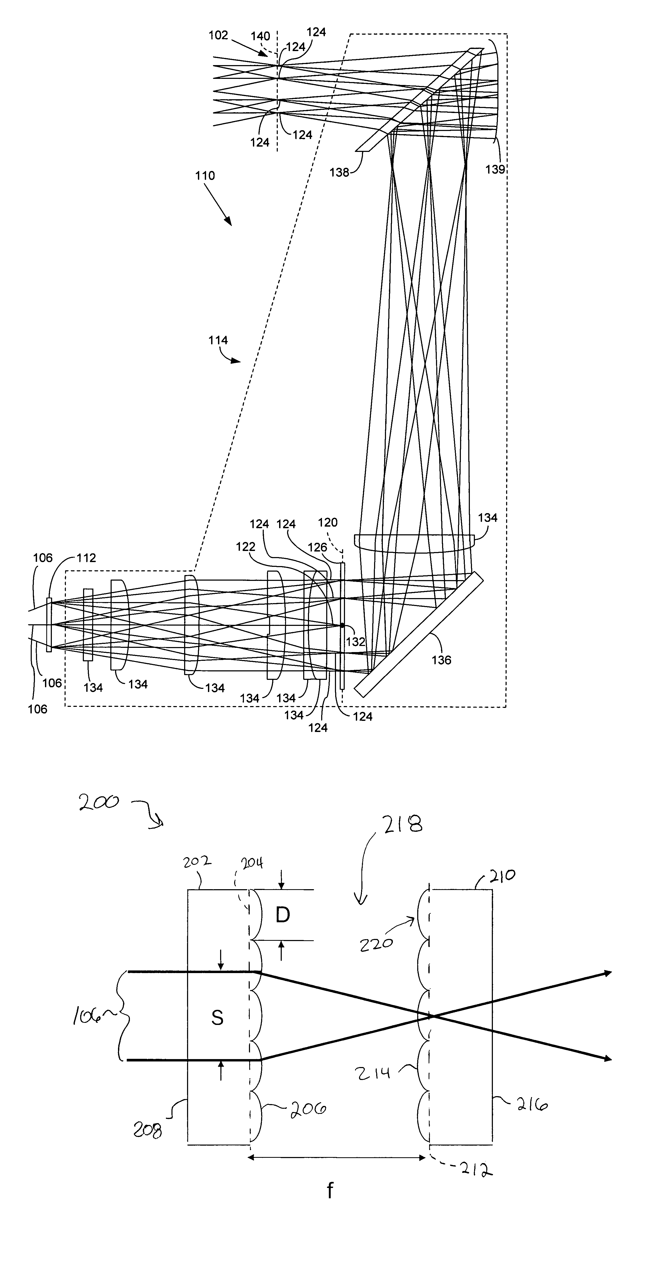
[0036]FIG. 3 is a diagram of a scanned-beam display system 100 that generates an exit pupil 102 having exit-pupil images (not shown in FIG. 3) of uniform or approximately uniform intensity according to an embodiment of the invention. The display system 100 includes an image-beam source 104 for generating an image beam 106, a scanning assembly 108 for scanning the beam 106, and a lens assembly 110. The assembly 110 includes a diffraction grating 112 for generating exit-pupil images having different intensities, and includes an ocular 114 for filtering the exit-pupil images from the grating 112 to generate the exit pupil 102. The lens assembly 110 is further discussed below in conjunction with FIGS. 4-14.

[0037]In operation of the display system 100, the source 104 modulates the beam 106 to generate pixels of a scanned image (not shown in FIG. 3), and the scanning assembly 108 scans the modulated beam 106 onto the diffraction grating 112. Although multiple paths of the scanned beam 106...


PUM


Abstract

A beam multiplier includes a beam-multiplying layer and an adjacent optical layer. The beam-multiplying layer is operable to generate output beamlets of light from an input beam of light, and the optical layer has an adjustable index of refraction. By switching the index of refraction of the optical layer between first and second values, one can switch the beam multiplier to a first state (e.g., “on”) where it generates the output beamlets of light, and can switch the beam multiplier to a second state (e.g., “off”) where it passes the input beam of light but does not generate the output beamlets. And by using the beam multiplier as an exit-pupil expander, one can switch the exit-pupil expander to a first state where it generates multiple exit-pupil images, and to a second state where it generates only a single exit-pupil image.

Description

PRIORITY CLAIM[0001]The present application claims priority from commonly owned U.S. patent application Ser. No. 10 / 205,858, filed Jul. 26, 2002 and U.S. patent application Ser. No. 10 / 206,177, filed Jul. 26, 2002, both of which claim priority to commonly owned U.S. provisional patent application Ser. No. 60 / 350,089, filed Nov. 2, 2001. The present application also claims priority from commonly owned U.S. provisional application Ser. No. 60 / 565,059, filed Apr. 23, 2004. All of these referenced applications are incorporated herein by reference.RELATED APPLICATIONS[0002]This application is related to commonly owned U.S. patent application Ser. No. 10 / 205,858, titled “APPARATUS AND METHODS FOR GENERATING MULTIPLE EXIT-PUPIL IMAGES IN AN EXPANDED EXIT PUPIL”, which is incorporated by reference and was filed on the same day as this application.FIELD OF THE INVENTION[0003]The invention relates generally to image display / projection systems, and more particularly to an apparatus such as a v...

Claims


Application Information

Patent Timeline
Patent Type & Authority Patents(United States)
IPC IPC(8): G02B5/18G02B3/00G02B26/08G02B26/10G02B27/00G02B27/01G02B27/09G02B27/10
CPCG02B3/0062G02B5/1871G02B27/0081G02B27/017G02B27/0927G02B27/0944G02B27/0961G02B2027/014
Inventor UREY, HAKANTEGREENE, CLARENCE T.
Owner MICROVISION
Why Eureka
Try Eureka