
Recoil system for the forend of a firearm

a recoil system and recoil technology, applied in the field of recoil systems for rifles and shotguns, can solve the problems of pain and/or bruising in the shoulder area of the affecting the person firing the weapon, and the shooter raising the front of the firearm, so as to achieve the effect of reducing the pain in the shoulder area of the person

Active Publication Date: 2008-03-11
VISTA OUTDOOR OPERATIONS
View PDF10 Cites 37 Cited by
  • Summary
  • Abstract
  • Description
  • Claims
  • Application Information

AI Technical Summary

Benefits of technology

[0017]Another benefit of having the recoil reduction system mounted in front of the receiver is that in the version with the handgrip extending downwardly, the handgrip has little or no recoil to it when the firearm is fired. Therefore when incorporating a light mounting portion on the front of the substantially stationary hand gripping member, the light projected forwardly maintains a stable beam of light.

Problems solved by technology

One age-old problem that has existed with firearms is the fact that many of them have a severe recoil that affects the person firing the weapon.
In firearms such as shotguns and rifles, the rear end of the butt stock is positioned against the shooter's shoulder and recoil often causes the shooter to raise the front of the firearm each time the weapon is fired.
Also recoil varies depending upon the amount of explosive being fired and the recoil can result in pain and / or bruising to the shoulder area of the person firing the weapon.
One example of the recoil being detrimental to a shooter's accuracy is where the firearm is a shotgun being used for skeet shooting by a male or a female.
In the past, the best prior art recoil systems for the butt stock of a firearm have been very expensive and the inexpensive systems did not function properly.
Two examples of expensive systems are a hydro-coil fluid dampening system and a pneumatic air chamber system.
If the compression coil spring is not strong enough it is worse, in that it gives the gun some travel and it is the same as holding the butt stock too loosely.

Method used


Image

  • Recoil system for the forend of a firearm
  • Recoil system for the forend of a firearm
  • Recoil system for the forend of a firearm

Examples


Embodiment Construction

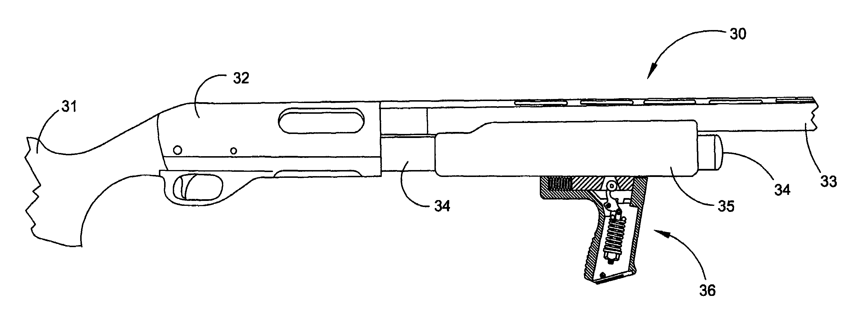
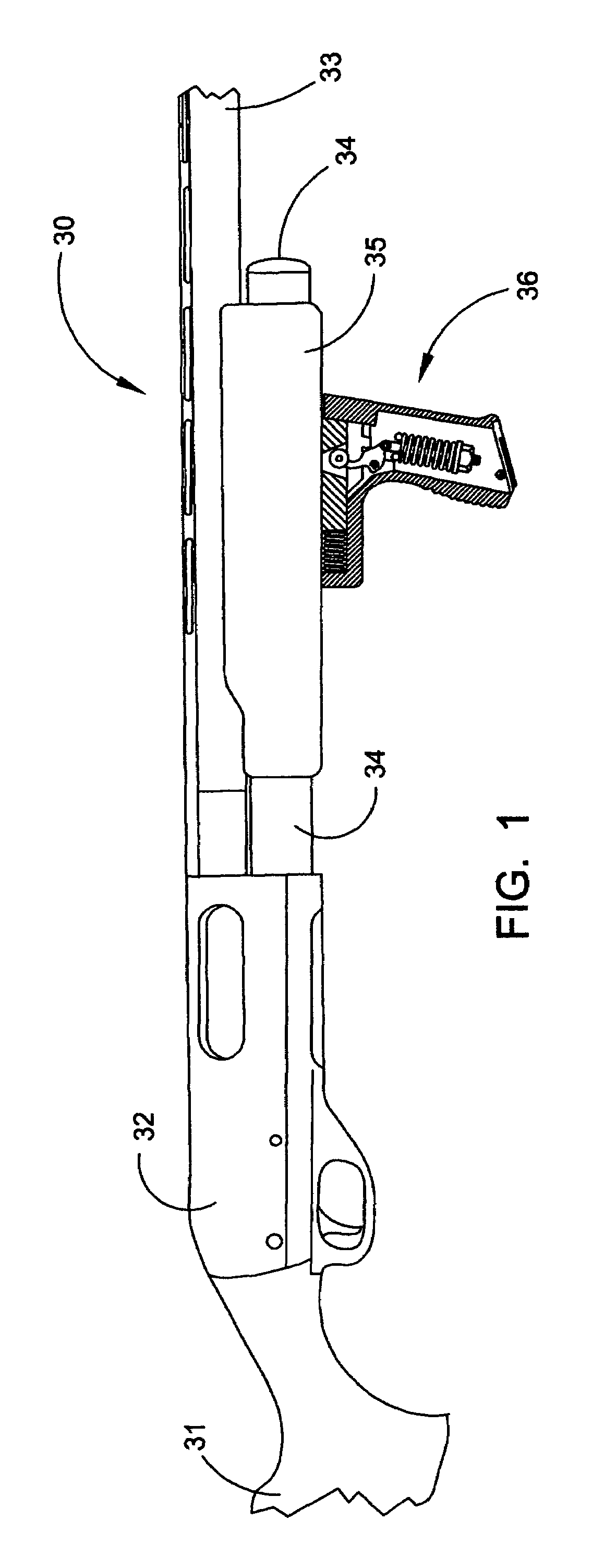
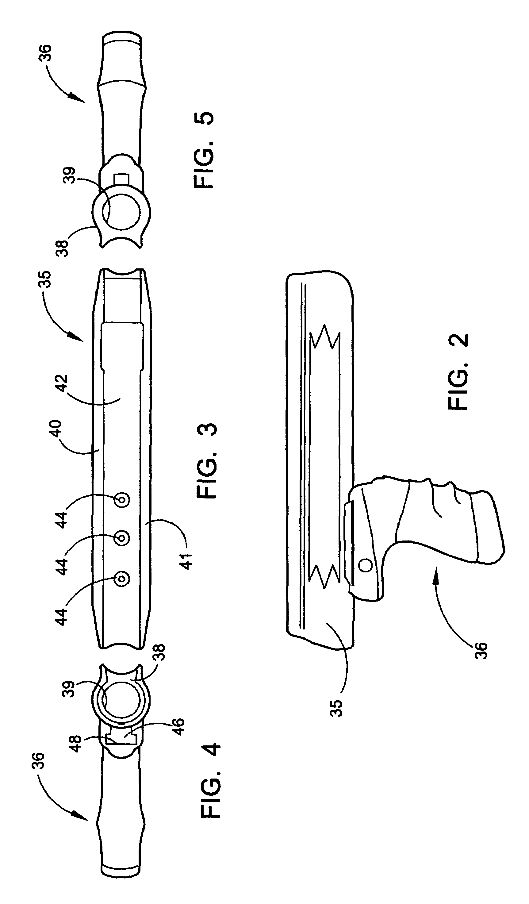
[0045]The novel recoil reduction system for a firearm will now be described by referring to FIGS. 1-9 and 18-19. A shotgun 30 is illustrated in FIG. 1 having butt stock 31, a receiver 32, a gun barrel 33, a magazine 34, a forend 35 and a handgrip member 36. The recoil reduction system is mounted within handgrip member 36.

[0046]FIGS. 2-5 and 18-19 illustrate views of the forend 35 from various sides and angles. FIG. 4 is a rear elevation view and it shows that forend 35 has a generally U-shaped transverse profile with a ring 38 formed at its front end. Ring 38 has a bore hole 39 that would telescope over magazine 34. The remainder of forend 35 has a left side wall 40, a right side wall 41 and a bottom wall 42. A plurality of screws 44 secure an inverted T-shaped rail 46 to the bottom surface of forend 35. Handgrip member 36 has a longitudinally extending inverted T-shaped track 48 along which rail 46 reciprocally travels. Track 48 has a chamber 49 formed in its rear end that receives...


PUM


Abstract

A recoil reduction system for the front end of a firearm, such as a shotgun or a rifle. In a first embodiment, the recoil reduction structure is mounted in a handgrip member secured to the bottom surface of the forend member. Various types of springs and cylindrical elastomer members can be utilized in various handgrip members. In a second embodiment the recoil reduction system is mounted in the forend member. In a third embodiment, the recoil reduction structure is utilized with a rifle having a long gun stock. The long gun stock has a butt portion, a middle portion and a front portion. The front portion is located forwardly of the receiver. A primary recess is formed in the bottom wall of the front portion and the recoil reduction structure is mounted therein. A cover member positioned over the primary recess hides the recoil reduction structure from view. A handle member may be secured to the bottom surface of the cover member and it may be retractable or rigidly positioned upright.

Description

BACKGROUND OF THE INVENTION[0001]The invention relates to firearms and more specifically to a recoil system for rifles and shotguns.[0002]One age-old problem that has existed with firearms is the fact that many of them have a severe recoil that affects the person firing the weapon. In firearms such as shotguns and rifles, the rear end of the butt stock is positioned against the shooter's shoulder and recoil often causes the shooter to raise the front of the firearm each time the weapon is fired. Also recoil varies depending upon the amount of explosive being fired and the recoil can result in pain and / or bruising to the shoulder area of the person firing the weapon. One example of the recoil being detrimental to a shooter's accuracy is where the firearm is a shotgun being used for skeet shooting by a male or a female.[0003]In the past, the best prior art recoil systems for the butt stock of a firearm have been very expensive and the inexpensive systems did not function properly. Two...

Claims


Application Information

Patent Timeline
IPC IPC(8): F41A21/26
CPCF41A25/10F41C23/06F41C23/16
Inventor BENTLEY, JAMES K.
Owner VISTA OUTDOOR OPERATIONS
Learn More