
Rotary application head and labelling installation for application of labels

a technology of label application and installation head, which is applied in the directions of manual label dispensers, transportation and packaging, packaging, etc., to achieve the effect of reducing the uptake of dir

Inactive Publication Date: 2008-03-11
NORDSON CORP
View PDF76 Cites 4 Cited by
  • Summary
  • Abstract
  • Description
  • Claims
  • Application Information

AI Technical Summary

Benefits of technology

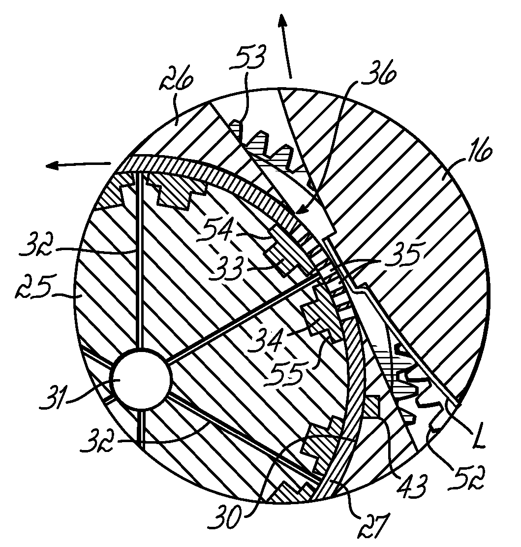
The patent describes a rotary application head for applying liquid adhesive, such as hot melt adhesive, to label strip material. The application head includes a housing with a cylindrical chamber that passes through it in an axially parallel application gap. The application head also includes a mask cylinder with outlet openings that expose the feed channel system in the feed cylinder. The invention allows for the efficient and precise application of adhesive to labels, particularly on cylindrical bodies such as bottles. The labelling installation includes an unrolling device for label strip material, a rotating vacuum drum for supplying labels, a cutting device for separating labels, and a rotating application head for liquid adhesive. The installation also includes a carousel for passing the cylindrical body past the vacuum drum with rotating means for the cylindrical bodies. The technical effects of the invention include improved efficiency and precision in label application and reduced dirt uptake on the label material.

Problems solved by technology

Rotary application heads of this type tend to take up dirt via the adhesive covered application areas and draw it into the rotary application head.

Method used


Image

  • Rotary application head and labelling installation for application of labels
  • Rotary application head and labelling installation for application of labels
  • Rotary application head and labelling installation for application of labels

Examples


Embodiment Construction

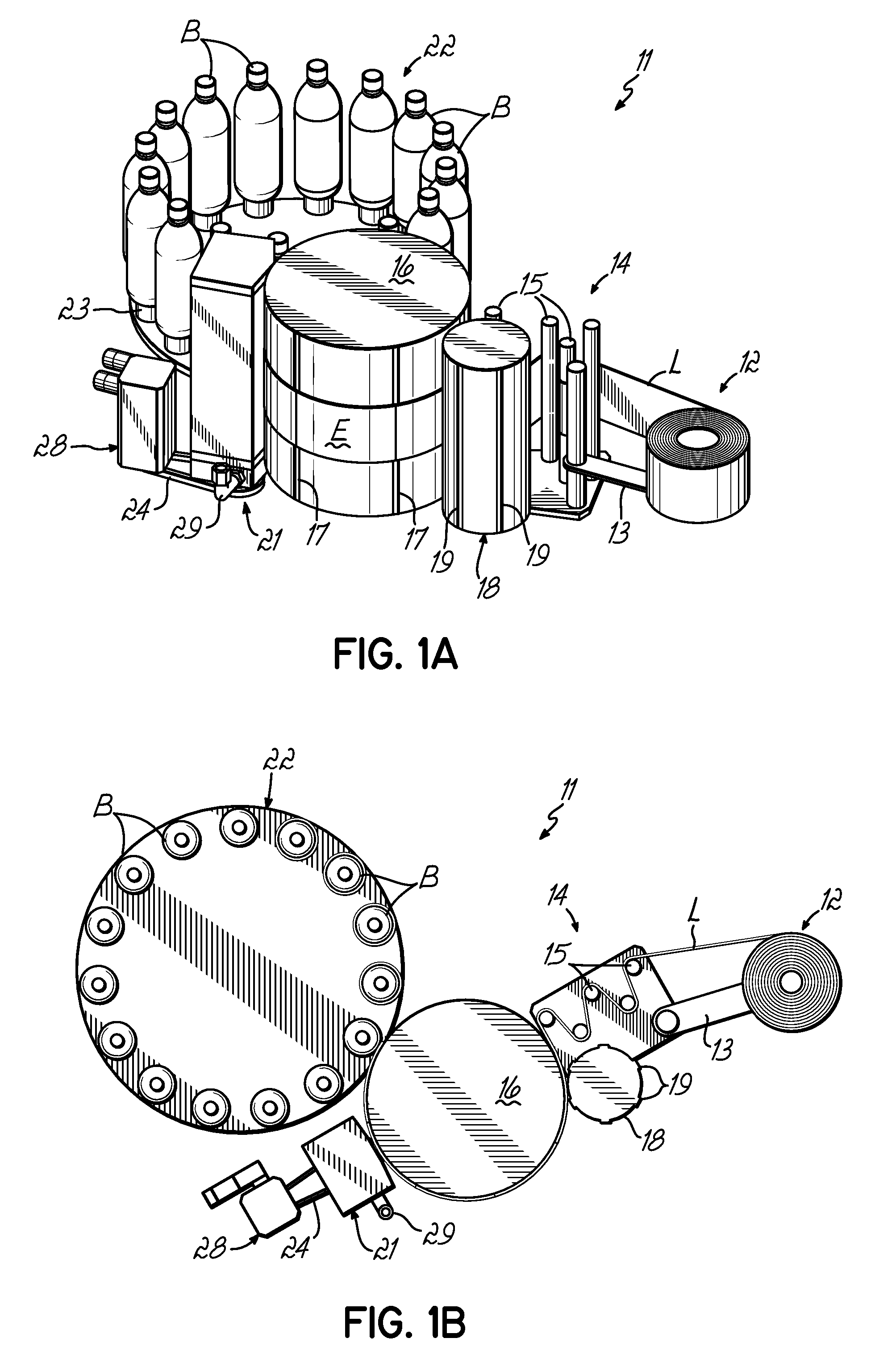
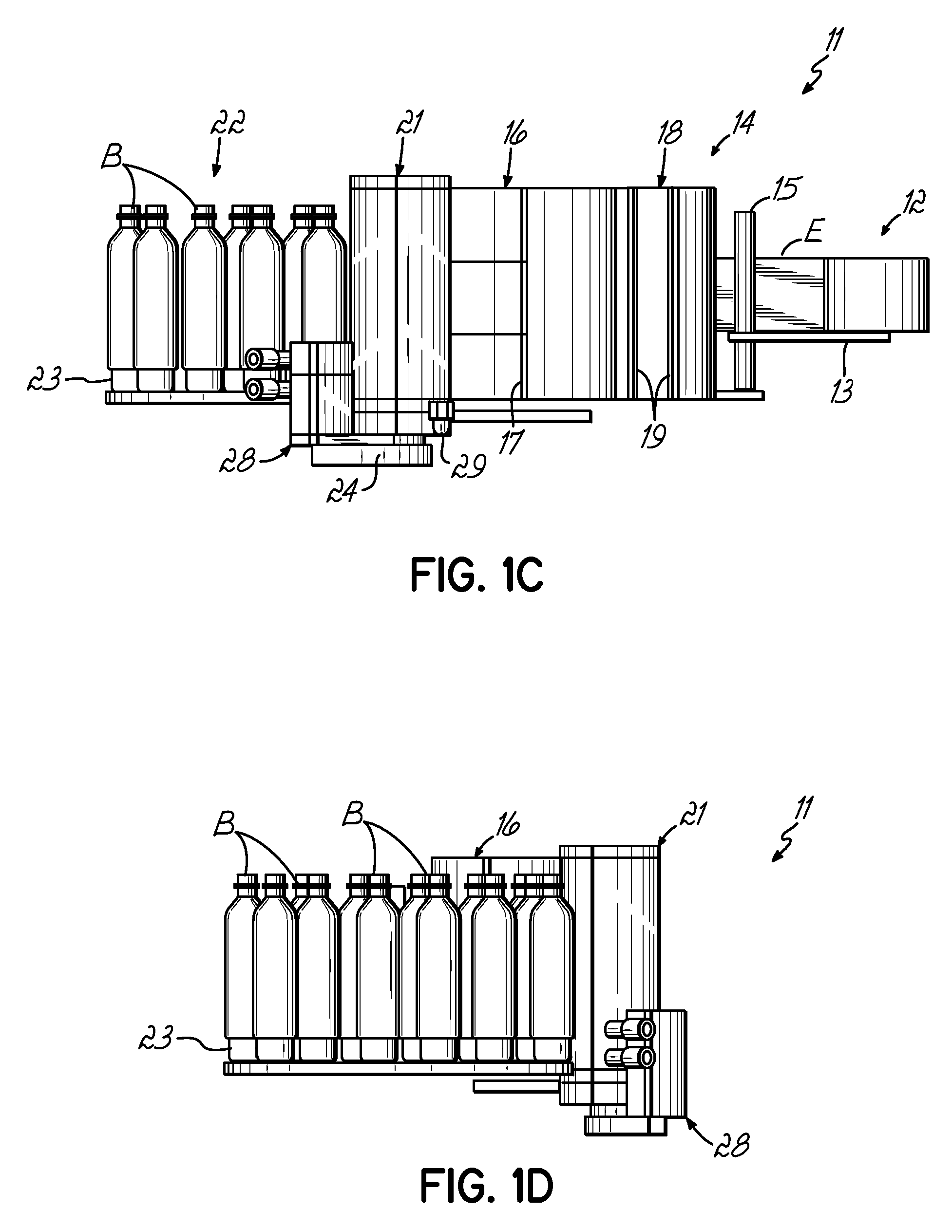
[0054]FIGS. 1A-D are subsequently described. A bottle labelling plant 11 according to the invention includes as substantial components an unrolling device 12 for label strip material L and a strip travel regulating arrangement 14 which can regulate the height position of the strip material L. The unrolling device 12 is supported by a roll retaining arm 13. The strip travel regulating arrangement 14 comprises individual deflecting rollers 15. The bottle labelling plant 11 further comprises a vacuum drum 16 on which individual axially parallel cutting edges 17, distributed on the circumference, can be seen. The vacuum drum 16 also has underpressure openings not shown in detail on its circumferential surface, which hold the strip material L or individual labels firmly on the vacuum drum 16. A cutting device 18 with a movable cutting blade 19 cooperates with the cutting edges 17 of the vacuum drum 16. By means of this cutting device 18 individual labels are separated from the strip mate...


PUM

PropertyMeasurementUnit
hot meltaaaaaaaaaa
lengthaaaaaaaaaa
circumferenceaaaaaaaaaa

Abstract

A system that applies strips of material, such as labels, to a cylindrical body, such as a bottle. The system includes a vacuum cylinder that holds the labels. The vacuum cylinder rotates bringing the labels into contact with a rotary application head that applies hot melt adhesive to the passing labels. The rotary application head includes a feed channel system that cooperates with a mask cylinder to controllably apply the adhesive. The adhesive covered label then is fixed to a bottle or other device that is rotating in a carousel.

Description

TECHNICAL FIELD OF THE INVENTION[0001]The invention relates to a rotary application head for application of liquid adhesives, especially hot melt adhesives, on strip material which is running past, and a labelling installation for applying labels to cylindrical bodies, such as bottles.BACKGROUND OF THE INVENTION[0002]Rotary application heads for known bottle labelling installations have a rotating roller having adhesive placed two-dimensionally on certain application areas in the interior of the housing. The application areas of the rotating roller having the adhesive are then brought in contact with passing label material. In this case, the rotating roller emerges from the housing in the area of an application gap so that contact with the label material takes place immediately. Rotary application heads of this type tend to take up dirt via the adhesive covered application areas and draw it into the rotary application head.[0003]Accordingly, it is one object of the present invention...

Claims


Application Information

Patent Timeline
Patent Type & Authority Patents(United States)
IPC IPC(8): B65C11/00B05B15/04B05C5/02B32B39/00
CPCB05C1/10B05C1/165B65C9/226B05C5/0258B05C1/027B05C5/0233Y10T156/1339B65C2009/0075Y10T156/1322Y10T156/1798
Inventor PUFFE, WOLFGANGLINGIER, ERIC
Owner NORDSON CORP
Learn More