Hydraulic flow control system with an internal compensator sleeve

a flow control system and compensator technology, applied in the direction of drilling casings, drilling pipes, borehole/well accessories, etc., can solve the problems of uncontrolled high pressure fluids and gases flowing, serious injury to personnel, and detrimental environmental repercussions, so as to prevent equipment damage, prevent fires, and operate quickly and efficiently

Inactive Publication Date: 2008-03-11
SYDNEY PERTH L L C
View PDF9 Cites 30 Cited by
  • Summary
  • Abstract
  • Description
  • Claims
  • Application Information

AI Technical Summary

Benefits of technology

[0006]The present invention utilizes a previously-described three-stage double-acting hydraulic extension system to hold and stab a safety valve into the top of a drill pipe or tubing during a high pressure situations. The hydraulic extension system can be mounted on a base with wheels, which move on a track. If a track cannot be used, the system can be mounted on lockable caster wheets. Mounted on the platform next to the hydraulic extension system may be a telescoping, mechanically-extending stanchion; a plate connects the top of the stanchion to the top of the hydraulic extension system. Attached to the hydraulic extension system is an extended arm to which a steel plate is attached, which has been drilled to hold the safety valve within an internal compensator sleeve, thereby allowing an operator to maintain a positive pin by box connection make up when floor slopes are uneven. Also attached to the hydraulic unit is a positioning arm, which is placed against the drill pipe or tubing in order to vertically align the safety valve. Alternatively, hydraulic tongs can be used. The length of both arms can be adjusted as necessary, by using the locking bolts or adjusting the hydraulic cylinders. When not in use, the arms are out of the way. When the system is activated, the extended arm is rotated into position to align the safety valve directly over the drill pipe or tubing. The three-stage double-acting hydraulic extension system can raise the extension arm high enough vertically (up to 12 feet) to allow the operator to stabilize the safety valve, then lower it, without exposing drilling personnel to the well's high pressures. Alternatively, an I-beam with gear track, or a screw drive system, can be used to raise and lower the safety valve. The hydraulic extension system can exert a downward force in excess of 10,000 pounds through the extension arm, thereby preventing an oil well blowout the possibility of a fire, and environmental damage. The optional stanchion, which extends and retracts along with the hydraulic extensions, prevents any rotational movement of the hydraulic extensions. After lowering the valve into the drill pipe or tubing, the hydraulic extension system can hold the valve in position while the operator makes up the safety valve pin by box connection with the drilling string and closes the well in. The arrangement of springs inside the compensator sleeve assembly gives it a moment of movement that allows the safety valve to “float” and tilt, in any direction. As a result, the pin of the safety valve can be threaded into the end of the drill pipe even when the rig floor is not level. Powered by hydraulics, a chan drive belt system rotates the safety valve, both clockwise and counterclockwise. Because the present invention greatly reduces the length of time required to install a safety valve in unexpected high pressure situations, its use greatly improves safety for drilling personnel.
[0008]It is another object of the present invention to provide an apparatus that is operated remotely, thereby keeping drill personnel away from hazardous conditions.
[0009]A further object of the present invention is to provide an apparatus with a compensator sleeve assembly, which allows the valve to tilt in any direction, making it possible for it to be screwed into the box end of a drill pipe, even when the rig floor slopes up to 100 in any direction.
[0010]It is still another object of the present invention to provide an apparatus which operates quickly and efficiently to bring a well under control.
[0011]Yet another object of the present invention is to prevent equipment damage, prevent fires, prevent environmental damage, and protect working personnel.

Problems solved by technology

When an oil well is being drilled, drilling personnel may encounter an unexpected high pressure situation requiring them to install a safety valve into the top of the drill pipe or tubing, from which uncontrolled high pressure fluids and gases are flowing.
However, higher pressures can result in serious injury to personnel, either by movement of the suspended safety valve or impact from blown fragments of sand and gravel.
If a safety valve cannot be installed, the only recourse is to allow the blowout to continue until the pressurized fluids are exhausted, or until the formation collapses, with detrimental environmental repercussions.

Method used


Image

  • Hydraulic flow control system with an internal compensator sleeve
  • Hydraulic flow control system with an internal compensator sleeve
  • Hydraulic flow control system with an internal compensator sleeve

Examples


Embodiment Construction

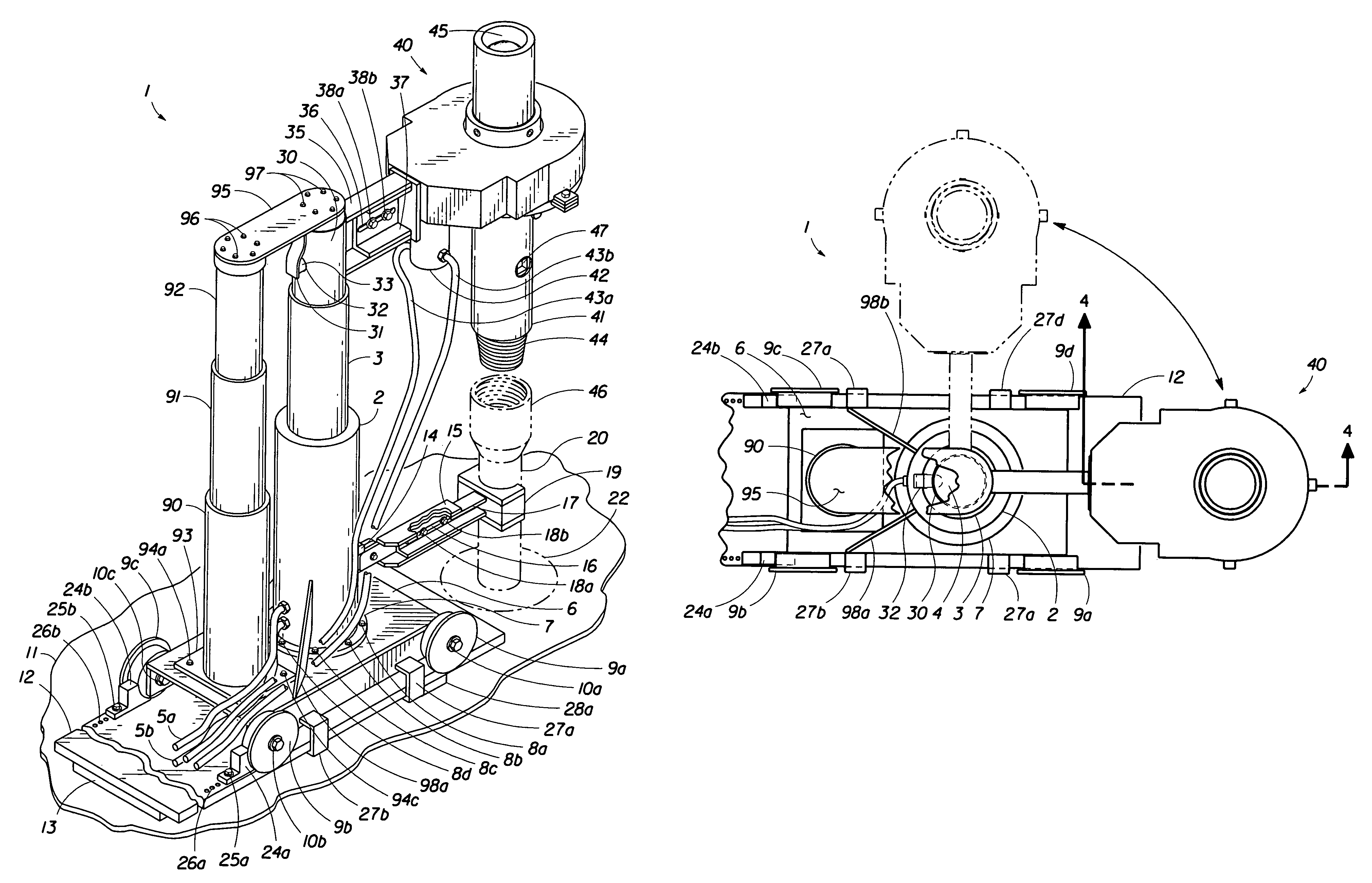
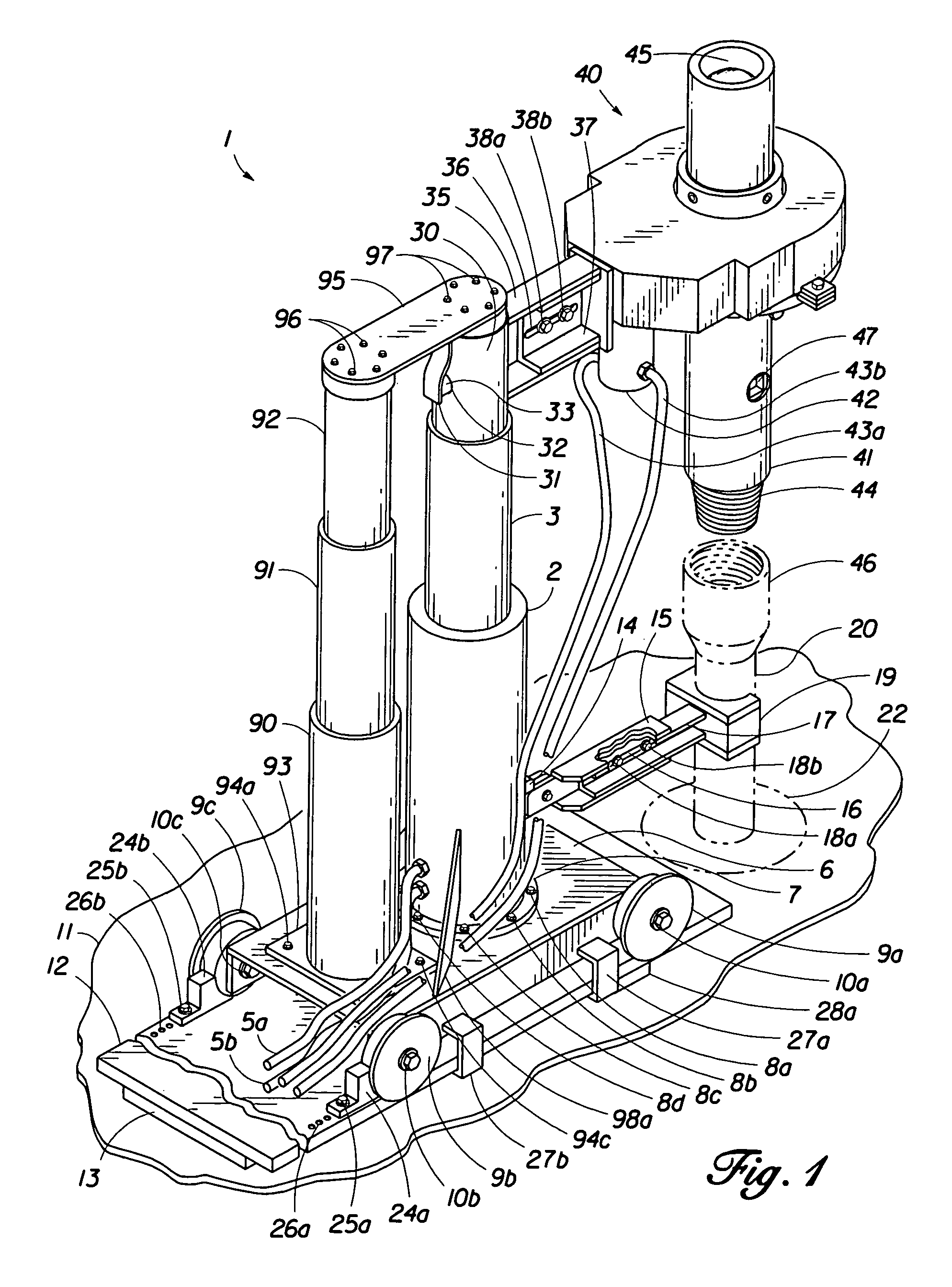
[0025]Referring to FIG. 1, the apparatus 1 of the present invention is shown in an operational position. The apparatus utilizes a three-stage double-acting, telescoping, hydraulic extension system, comprising a stainless steel hydraulic unit 2 with a first hydraulic cylinder extension 3 and a second hydraulic cylinder extension 4 telescoping upwardly, with power supplied by a remote hydraulic pump (not shown) through hydraulic hoses 5a, 5b. The hydraulic unit 2 is supported by a base 6, and is attached thereto by base plate 7 with bolts 8a, 8b, 8c, 8d, 8e. A mechanically-extending, telescoping stanchion 90 is mounted on the base 6 next to the hydraulic unit 2. The machine-fit stainless steel stanchion 90, with a first stanchion extension 91 and a second stanchion extension 92, is attached to the base 6 by base plate 93 with bolts 94a, (94b), 94c, (94d). One end of a stabilizing plate 95 is bolted to the top of second stanchion extension 92 with bolts 96. The other end of stabilizing...


PUM


Abstract

A compensator sleeve assembly for use with a hydraulic extension system used to handle safety valves designed to shut off high pressure upward flow through drill pipe or tubing. The compensator sleeve assembly, amounted on an adjustable arm slide, has a steel sleeve for holding the safety valve, an arrangement of circumferentially space-apart spring sets which allow the safety valve to “float” and tilt from the vertical in any direction and a hydraulic-powered chain drive belt for rotating the safety valve.

Description

FIELD OF THE INVENTION[0001]The present invention relates to an improved apparatus for handling safety valves used for shutting off high pressure upward flow through drill pipe or tubing.BACKGROUND OF THE INVENTION[0002]When an oil well is being drilled, drilling personnel may encounter an unexpected high pressure situation requiring them to install a safety valve into the top of the drill pipe or tubing, from which uncontrolled high pressure fluids and gases are flowing.[0003]Various methods are presently used to attempt such installation. The methods share a common feature of positioning the safety valve over the drill pipe while the valve is suspended by a cable, chain or rope catline. Typically, drilling personnel are required to physically align the end of the safety valve (which can weigh from 50 to 300 pounds) with the top of the drill pipe (which may be 5 to 10 feet off the working floor), while fluids and gases are escaping. If flowing pressures do not exceed 50 psi, the pr...

Claims


Application Information

Patent Timeline
Patent Type & Authority Patents(United States)
IPC IPC(8): E21B19/16
CPCE21B19/16E21B21/106E21B34/02
Inventor MCDOWELL, BOBBY DEWAIN
Owner SYDNEY PERTH L L C
Why Eureka
Try Eureka