Tail lamp structure for vehicles

a technology for tail lamps and vehicles, applied in cycle equipments, lighting support devices, roads, etc., can solve problems such as the problem of further upsizing of the structure and the increase in the number of parts, and achieve the effect of further miniaturization and reduction in depth

Active Publication Date: 2008-03-11
HONDA MOTOR CO LTD
View PDF4 Cites 13 Cited by
  • Summary
  • Abstract
  • Description
  • Claims
  • Application Information

AI Technical Summary

Benefits of technology

[0011]It is an object of the present invention to solve the above-described problems and to provide a tail lamp structure for a vehicle which can correspond with the design for flexibility in the appearance, and can be reduced in depth. In addition, the problem relating to an increase in the number of components is solved to permit further miniaturization.

Problems solved by technology

In addition, in the tail lamp structure in the related art, since upper portions of the housing and the lens are covered by a tail cover, a different member (tail cover) is required for covering the tail lamp of the vehicle in the mounted state, which results in an increase in the number of parts.
Therefore, further upsizing of the structure has been a problem to be solved.

Method used


Image

  • Tail lamp structure for vehicles
  • Tail lamp structure for vehicles
  • Tail lamp structure for vehicles

Examples


Embodiment Construction

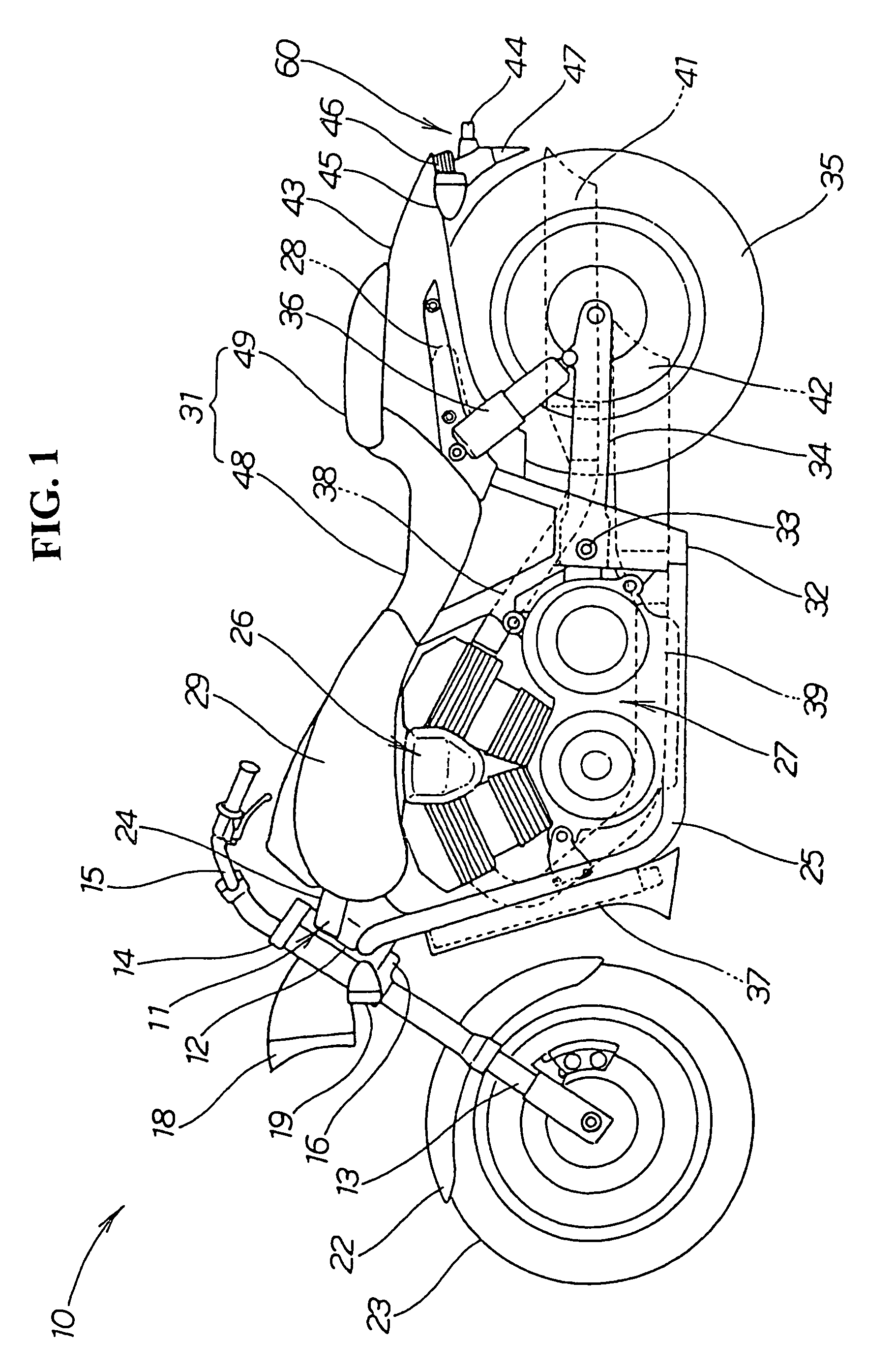
[0059]FIG. 1 is a side view of a vehicle in which a tail lamp structure according to the present invention is employed. A motorcycle 10 is configured by mounting a head pipe 12 to a vehicle body frame 11 with a front fork 13 steerably mounted on the head pipe 12. A steering handle 15 is provided on a top bridge 14 of the front fork 13. A head light 18 and left and right front winkers 19 (numeral 19 on the right side is not shown) are provided at a front portion between the top bridge 14 and a bottom bridge 16. A front fender 22 is provided together with a front wheel 23 mounted at a lower portion of the front fork 13. A main frame 24 of the vehicle body frame 11 extends rearwardly from the head pipe 12. A down tube 25 of the vehicle body frame 11 extends rearwardly from obliquely below. An engine 26 is mounted between the main frame 24 and the down tube 25. A transmission 27 is connected to the engine 26 with a fuel tank 29 positioned on the main frame 24. A seat rail 28 extends rea...


PUM


Abstract

In a vehicle that includes a rear fender for covering the upper portion of a rear wheel, a mud guard cover for covering the rear portion of the rear wheel, and a tail lamp arranged around the rear fender and the mud guard cover wherein the tail lamp includes light-emitting diodes as light sources, and includes a light-emitting diode board for placing the light-emitting diodes thereon, a control element board for placing a control element for controlling the light-emitting diodes thereon, a housing for collectively accommodating the light-emitting diode board and the control element board, and a lens for covering the housing and the control element board that is arranged downwardly of the light-emitting diode board.

Description

CROSS-REFERENCE TO RELATED APPLICATIONS[0001]The present application claims priority under 35 USC 119 to Japanese Patent Application No. 2004-297933 filed on Oct. 12, 2004 the entire contents of which are hereby incorporated by reference.[0002]1. Field of the Invention[0003]The present invention relates to a tail lamp structure for a vehicle.[0004]2. Description of Background Art[0005]A tail lamp structure for a vehicle is known wherein a light-emitting diode is used as a light source for improving visibility.[0006]In a tail lamp structure for a vehicle in which the light-emitting diodes are arranged on a board, the board and the light-emitting diodes are arranged in a housing, and a lens is used for covering the housing.[0007]A tail lamp structure for a vehicle as described above, is disclosed in JP-A-2002-337775, see page 8, FIG. 6.[0008]The tail lamp structure for a vehicle is significantly related to the design of its appearance. In addition, it is necessary to have high flexibi...

Claims


Application Information

Patent Timeline
Patent Type & Authority Patents(United States)
IPC IPC(8): B62J6/04F21W107/17
CPCB60Q1/0094B62J6/04F21S48/10F21W2111/02B62J50/26B62J15/00B62J6/26F21S43/26F21S43/14F21W2103/10B62J6/01F21S41/00
Inventor YAMAGUCHI, SEIJITAKANASHI, YOSHIHIRONAKAMURA, KENTANAKAYAMA, MASARU
Owner HONDA MOTOR CO LTD
Why Eureka
Try Eureka