LED unit for a vehicle lamp assembly

a technology for led arrays and vehicle lamps, which is applied in the field of vehicles, can solve the problems of large cost, small production scale of each array, and inability to universally install led arrays in various vehicles, and achieve the effects of low cost, convenient repair and/or replacement, and low cos

Inactive Publication Date: 2008-03-11
FORD GLOBAL TECH LLC +1
View PDF9 Cites 10 Cited by
  • Summary
  • Abstract
  • Description
  • Claims
  • Application Information

AI Technical Summary

Benefits of technology

[0011]One advantage of the invention is that an LED unit for a vehicle lamp assembly is provided that has a standardized construction for use in a variety of vehicle lamp assemblies and thus provides economy of scale.
[0012]Another advantage of the invention is that an LED unit for a vehicle lamp assembly is provided that is readily repaired and / or replaced at substantially low costs.
[0013]Yet another advantage of the invention is that an LED unit for a vehicle lamp assembly is provided that enhances vehicle styling and brand recognition.
[0014]Still another advantage of the invention is that an LED unit for a vehicle lamp assembly is provided that consumes substantially small amounts of energy.
[0015]Yet another advantage of the invention is that an LED unit for a vehicle lamp assembly is provided that is efficiently packaged for increasing available space for the engine compartment, cargo storage, passenger cabin, and other vehicle structures.
[0016]Still another advantage of the invention is that an LED unit for a vehicle lamp assembly is provided that maintains a substantially high lumen output over a significant period of time.

Problems solved by technology

In this regard, the customized construction of the LED array cannot be universally installed within various vehicles, which typically have lamp assemblies with distinct shapes and sizes.
Therefore, each array may be produced on a relatively small-scale basis and at significant costs.

Method used


Image

  • LED unit for a vehicle lamp assembly
  • LED unit for a vehicle lamp assembly
  • LED unit for a vehicle lamp assembly

Examples


Embodiment Construction

[0029]In the following figures, the same reference numerals are used to identify the same components in the various views.

[0030]The present invention is particularly suited for an LED unit for an exterior rear vehicle lamp assembly. In this respect, the embodiments described herein employ structural features where the context permits. However, various other embodiments are contemplated having different combinations of the described features, having additional features other than those described herein, or even lacking one or more of those features. For instance, the LED unit can be integrated within an exterior front vehicle lamp assembly as desired.

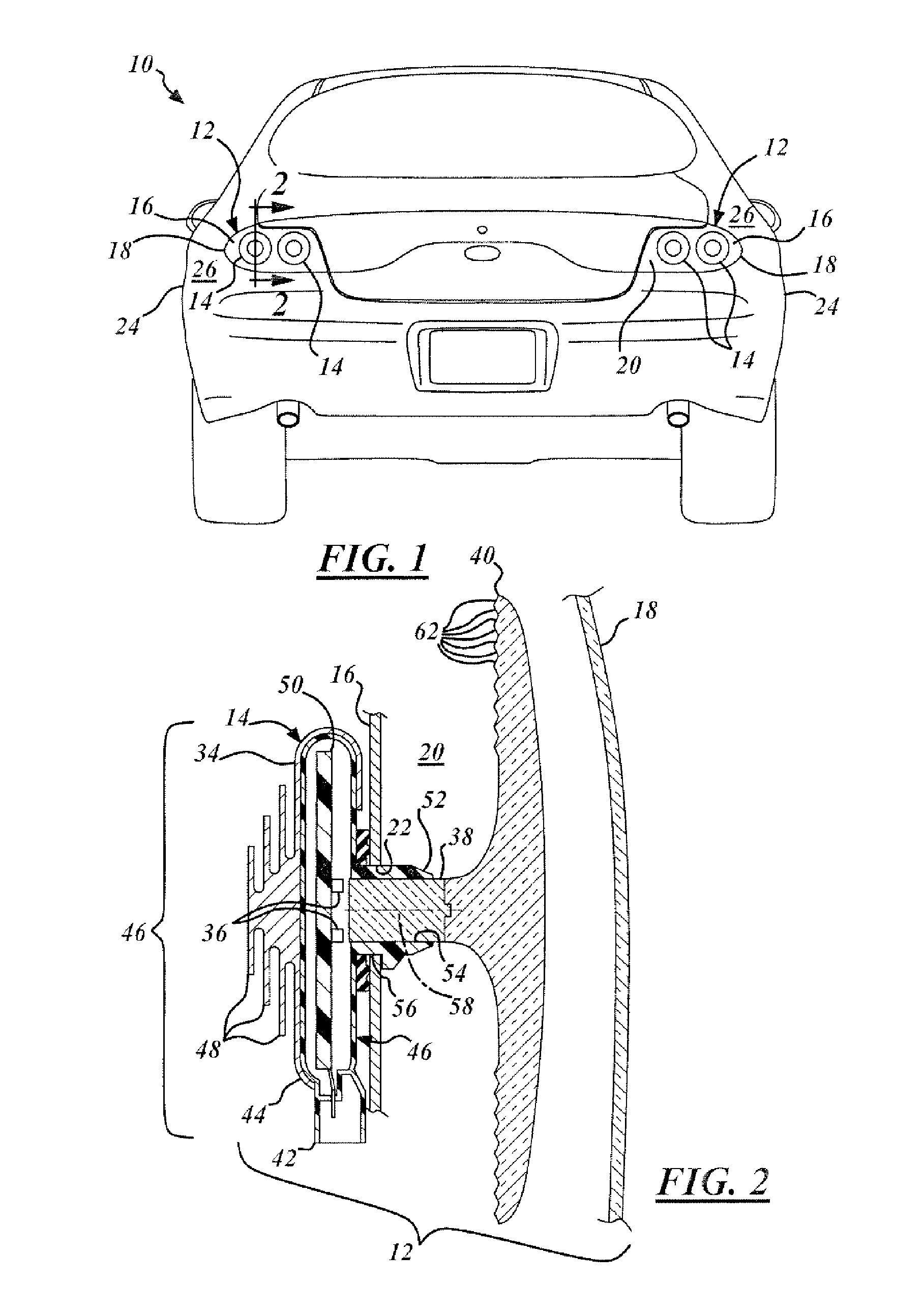
[0031]Referring to FIG. 1, there is shown a rear plan view of a vehicle 10 having two (2) lamp assemblies 12, each with a pair of light emitting diode units 14 (“LED units”).

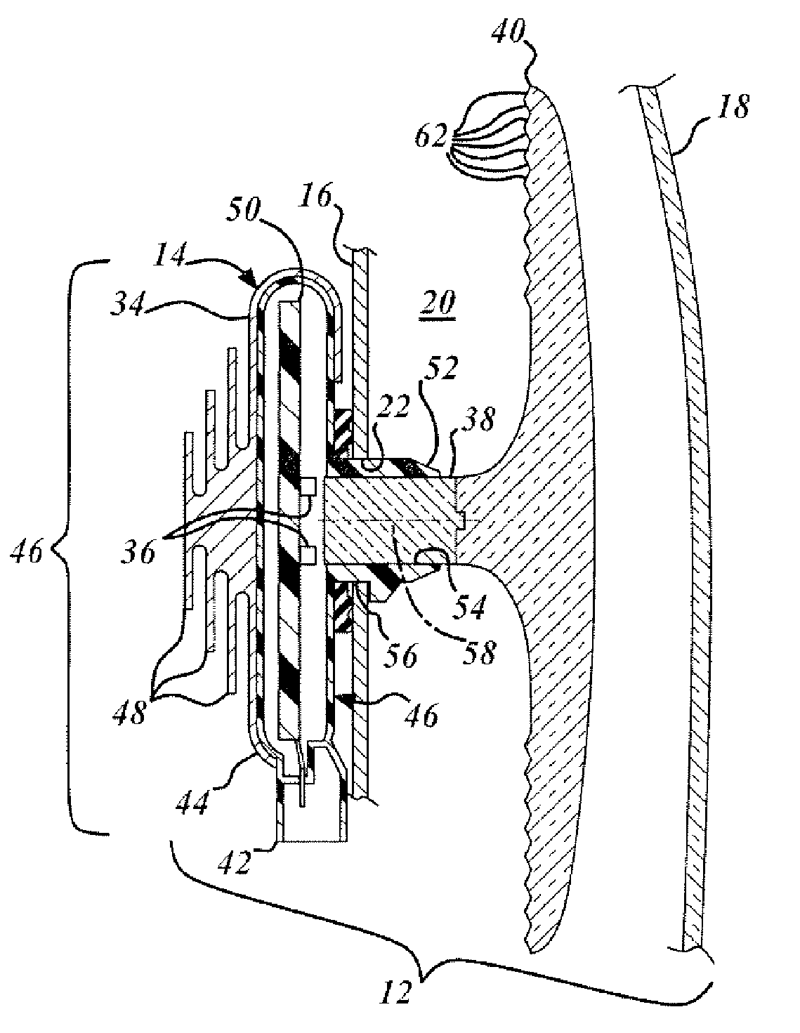
[0032]With attention to FIG. 2, each lamp assembly 12 is comprised of a base portion 16, a clear lens cover 18, a lamp cavity 20 therebetween, and one or more LED un...


PUM


Abstract

An LED unit for a vehicle lamp assembly. The LED unit is comprised of a housing, one or more LEDs, a light pipe, and an optic structure. The housing contains the LEDs and has the light pipe extending therefrom. The light pipe is sized sufficiently narrow for extending through a hole formed in a base portion of the vehicle lamp assembly. The light pipe is attached to an optic structure. The vehicle lamp assembly transmits light in a unilateral direction distal to the housing through the light pipe and the optic structure. The optic structure scatters light in a series of directions distal to the housing.

Description

TECHNICAL FIELD[0001]The present invention relates generally to vehicles, and more particularly to an LED unit for a vehicle lamp assembly.BACKGROUND[0002]Automotive manufacturers are investigating light emitting diodes (LEDs) for vehicle lamp systems in view of LED efficiency, durability, long life, in addition to compact packaging and design opportunities associated therewith. LEDs are solid-state semiconductor devices that convert electrical energy directly into a predetermined color of light.[0003]LEDs typically are efficient for consuming less power than conventional light sources, such as filament bulbs and neon lamps. For instance, a typical LED can consume as little as one Watt while a filament bulb can consume 25 Watts and a neon bulb can consume 116 Watts.[0004]Furthermore, LEDs typically offer significant resistance to shock and vibration and may thus provide more than 10,000 hours of life. It is understood that these benefits can decrease the cost of warranties.[0005]Mor...

Claims


Application Information

Patent Timeline
Patent Type & Authority Patents(United States)
IPC IPC(8): F21V9/00F21W107/10
CPCB60Q1/2696F21S48/2237F21V29/76F21V29/75F21S48/2268F21S48/215F21S48/328F21V29/004F21S43/14F21S43/237F21S43/245F21S45/47F21V29/767
Inventor BASILE, JIMDASSANAYAKE, MAHENDRACLEMENT, CHAD
Owner FORD GLOBAL TECH LLC
Why Eureka
Try Eureka