
Torque transmitting assembly and method of producing

a transmission assembly and transmission technology, applied in the direction of gearing elements, toothed gearings, gearings, etc., can solve the problems of fracture and failure of components, large cross-section of the portion of the pinion carrier that separates the retaining faces, and difficulty in forming the pinion-carrier portion of the assembly, so as to facilitate the transfer of rotation, maximize production efficiency, and minimize weight and production costs

Active Publication Date: 2008-03-11
METAL FORMING & COINING
View PDF10 Cites 13 Cited by
  • Summary
  • Abstract
  • Description
  • Claims
  • Application Information

AI Technical Summary

Benefits of technology

[0012]Consistent and consonant with the present invention, a torque transmitting assembly wherein production efficiency is maximized and weight and production costs are minimized, has surprisingly been discovered. The torque transmitting assembly comprises: a generally cup shaped outer shell having a closed end and an open end, the closed end having at least one slot formed therein, the open end of the outer shell adapted to be operatively engaged with a first rotating member; and a generally disk shaped inner member having a central aperture and a central axis, the inner member including at least one tab extending axially outwardly therefrom and engaging the slot of the outer shell to facilitate a transfer of rotation between the outer shell and the inner member, the central aperture adapted to be operatively engaged with a second rotating member.

Problems solved by technology

In respect of the practices listed above, several problems are experienced in forming the pinion-carrier portion of the assembly.
Due to the brittle nature of powdered metal parts, the cross-section of the portion of the pinion carrier that separates the retaining faces must be structurally large.
This density variation, along with the concurrent thickness change in the same area, results in a stress riser that frequently causes fracture and failure of the component.
This results in increased weight and space consumption, both of which are expensive and undesirable in an automatic transmission environment.
However, there is no ability to significantly change the material thickness for any component of the assembly.
The result is excess mass and space consumption, although it represents a large improvement in these aspects as compared to parts produced from powdered metal.
The biggest weakness of stamped parts is the lack of stiffness.
Under heavy loading, the stamped parts frequently deflect to the point that the gears may become misaligned causing undesirable noise and wear.
However, cold forming is somewhat limited in its ability to create long extrusions cost-effectively.
Additionally, the torque transmitting method used in the pinion carrier and drive shell assembly also results in addition of materials causing increased weight and space consumption.

Method used


Image

  • Torque transmitting assembly and method of producing
  • Torque transmitting assembly and method of producing
  • Torque transmitting assembly and method of producing

Examples


Embodiment Construction

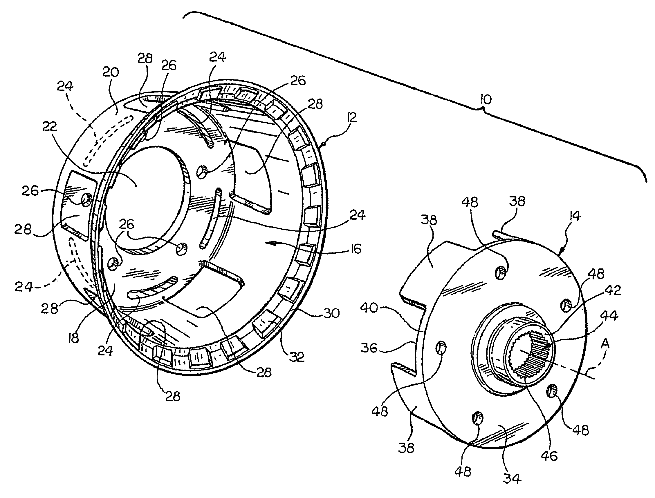
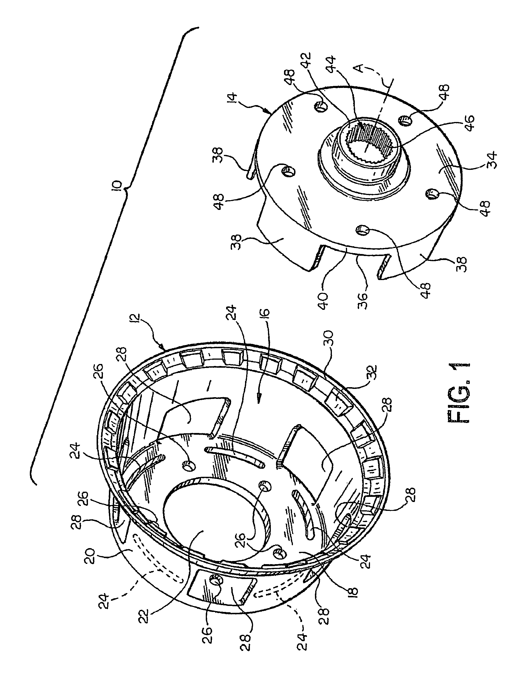
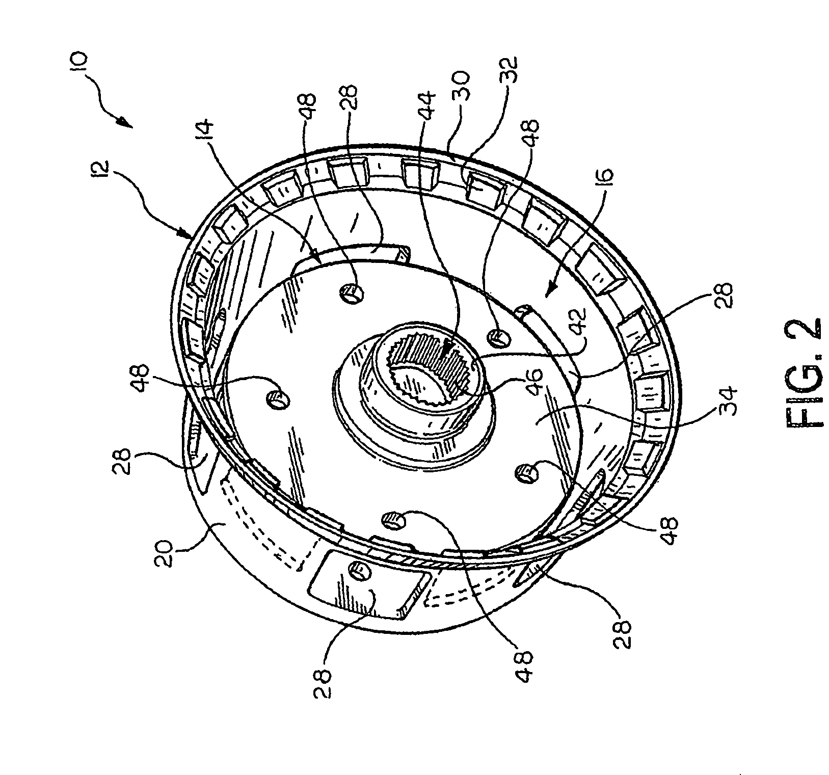
[0017]Referring now to the drawings, and particularly FIG. 1, there is shown generally at 10 an exploded perspective view of a pinion carrier and drive shell assembly or torque transmitting assembly incorporating the features of the invention. The pinion carrier and drive shell assembly 10 includes a drive shell 12 and a pinion carrier 14.

[0018]The drive shell 12 is a generally cup shaped or bowl shaped outer shell having an open end 16, a closed end 18, and an outer wall 20. The closed end 18 of the drive shell 12 includes a central aperture 22 formed therein. An annular array of slots 24 is formed in the closed end 18 and surrounds the aperture 22. Holes 26 are interposed between adjacent slots 24 to form an annular array of the holes 26 around the aperture 22 of the closed end 18. A plurality of access holes 28 is formed in the outer wall 20 of the drive shell 12. In the embodiment shown, the access holes 28 are formed adjacent the holes 26 to provide access thereto and facilitat...


PUM


Abstract

An improvement in manufacturing and resulting structure of a torque transmitting assembly for use in a vehicle transmission which transmits torque from a first rotating member to a second rotating member wherein production efficiency is maximized and production costs are minimized.

Description

CROSS-REFERENCE TO RELATED APPLICATION[0001]This application is a 371 of PCT / US04 / 00903, filed Jan. 14, 2004, which claims the benefit of U.S. provisional patent application Ser. No. 60 / 440,110, filed Jan. 15, 2003.FIELD OF THE INVENTION[0002]The present invention relates to a torque transmitting assembly and a method of making the same and more particularly a combined pinion carrier and drive shell and a method of making the same.BACKGROUND OF THE INVENTION[0003]A pinion carrier is a support structure that locates pinion (or planet) gears in a planetary gear set and transmits torque to other components within a vehicle transmission. A drive shell or planet carrier is a tubular metal component that carries torque from the pinion carrier to another component axially displaced from the pinion carrier in the transmission. The drive shell also revolves around the central axis of the pinion carrier and supports the pinion gears.[0004]Some known methods for producing a pinion carrier incl...

Claims


Application Information

Patent Timeline
Patent Type & Authority Patents(United States)
IPC IPC(8): F16H57/08F16HF16H3/44F16H57/02
CPCF16H57/082F16H3/44
Inventor HUBER, DAVID P.VASA, BEN R.CRIPSEY, TIMOTHY J.
Owner METAL FORMING & COINING
Learn More