Spatial light modulator with integrated optical compensation structure

a technology of optical compensation structure and spatial light, which is applied in the direction of optics, instruments, optical elements, etc., can solve the problems of increasing the difficulty of fabricating them by current manufacturing process flow, and achieve the effect of improving the manufacturing and performance of spatial light modulators

Inactive Publication Date: 2008-03-11
SNAPTRACK
View PDF10 Cites 102 Cited by
  • Summary
  • Abstract
  • Description
  • Claims
  • Application Information

AI Technical Summary

Problems solved by technology

As spatial light modulators become increasingly sophisticated, the inventor anticipates that difficulties associated with fabricating them by current manufacturing process flows will also increase.

Method used


Image

  • Spatial light modulator with integrated optical compensation structure
  • Spatial light modulator with integrated optical compensation structure
  • Spatial light modulator with integrated optical compensation structure

Examples


Embodiment Construction

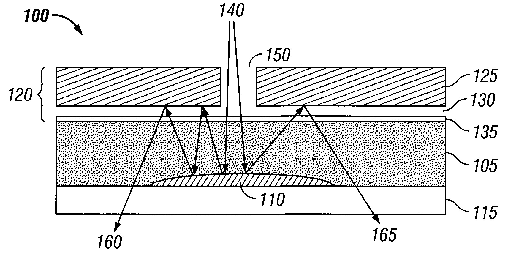
[0029]A preferred embodiment is an interferometric modulator that includes at least one integrated optical compensation structure. In some configurations, the optical compensation structure is arranged between the substrate and the light-modulating elements of the interferometric modulator. In other configurations, the light-modulating elements are arranged between the substrate and the optical compensation structure.

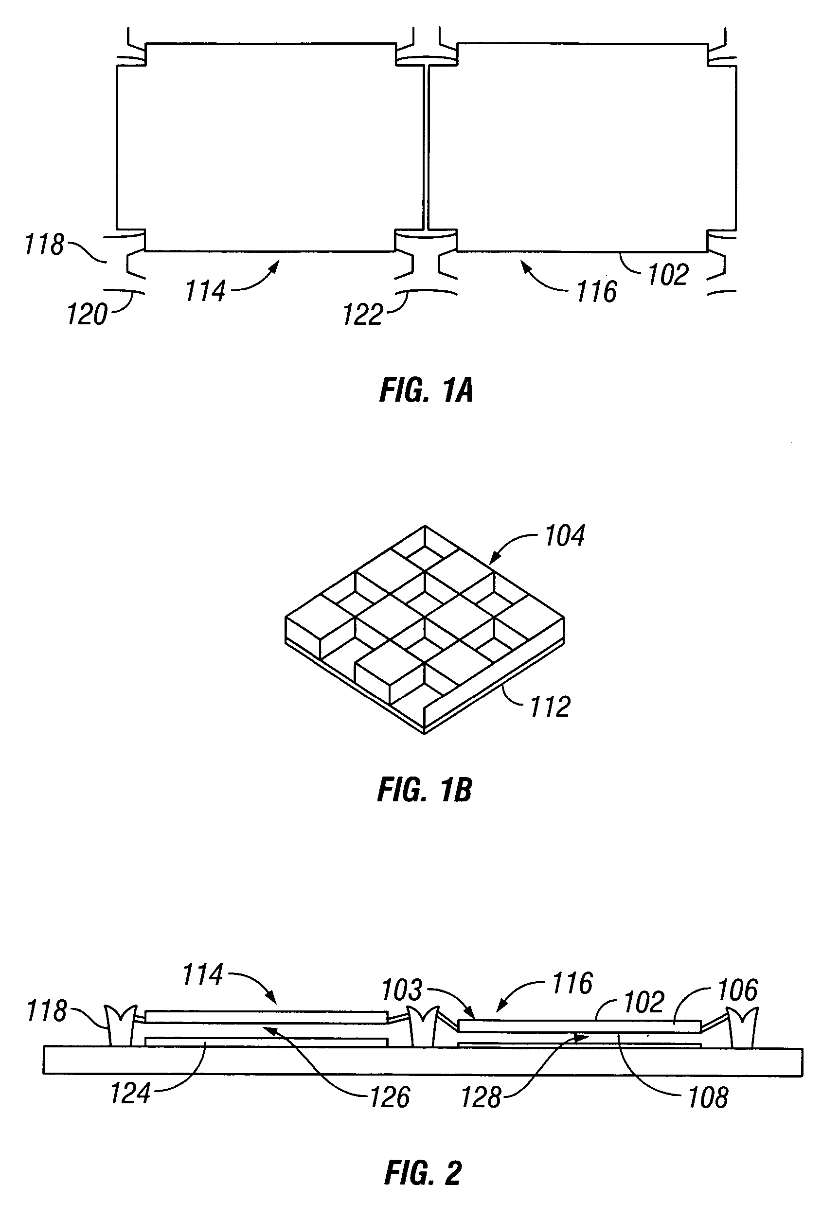
[0030]Various examples of interferometric modulators are described in U.S. Patent Publication No. 2002 / 0126364 A1. FIGS. 1 and 2 illustrate some characteristics of a typical interferometric modulator (see FIGS. 1 and 2 of U.S. Patent Publication No. 2002 / 0126364 A1and the corresponding text). Referring to FIGS. 1A and 1B, two interferometric modulator structures 114 and 116 each include a secondary mirror 102 with a corrugated pattern 104 etched into its upper (outer) surface 103, using any of a variety of known techniques. The corrugation does not extend through the me...


PUM

PropertyMeasurementUnit
angle of incidenceaaaaaaaaaa
transparentaaaaaaaaaa
bias voltageaaaaaaaaaa

Abstract

A spatial light modulator comprises an integrated optical compensation structure, e.g., an optical compensation structure arranged between a substrate and a plurality of individually addressable light-modulating elements, or an optical compensation structure located on the opposite side of the light-modulating elements from the substrate. The individually addressable light-modulating elements are configured to modulate light transmitted through or reflected from the transparent substrate. Methods for making such spatial light modulators involve fabricating an optical compensation structure over a substrate and fabricating a plurality of individually addressable light-modulating elements over the optical compensation structure. The optical compensation structure may be a passive optical compensation structure. The optical compensation structure may include one or more of a supplemental frontlighting source, a diffuser, a black mask, a diffractive optical element, a color filter, an anti-reflective layer, a structure that scatters light, a microlens array, and a holographic film.

Description

CROSS-REFERENCE TO RELATED APPLICATIONS[0001]This application claims priority to U.S. Provisional Patent Application Ser. No. 60 / 541,607, filed Feb. 3, 2004; U.S. Provisional Patent Application Ser. No. 60 / 613,482, filed Sep. 27, 2004; U.S. Provisional Patent Application Ser. No. 60 / 613,536, filed Sep. 27, 2004; and U.S. Provisional Patent Application Ser. No. 60 / 613,542, filed Sep. 27, 2004; all of which are hereby incorporated by reference in their entireties.BACKGROUND[0002]1. Field of the Invention[0003]This invention relates to improvements in the manufacturing and performance of spatial light modulators such as interferometric modulators.[0004]2. Description of the Related Art[0005]Spatial light modulators are display devices that contain arrays of individually addressable light modulating elements. Examples of spatial light modulators include liquid crystal displays and interferometric modulator arrays. The light modulating elements in such devices typically function by alter...

Claims


Application Information

Patent Timeline
Patent Type & Authority Patents(United States)
IPC IPC(8): G02B26/00G02F1/1335G02F1/136
CPCG02F1/1335G02B26/001G02F1/13356G02B26/00G02F1/136G02F1/21
Inventor CHUI, CLARENCESAMPSELL, JEFFREY B.CUMMINGS, WILLIAM J.TUNG, MING-HAU
Owner SNAPTRACK
Why Eureka
Try Eureka