Eureka AIR delivers breakthrough ideas for toughest innovation challenges, trusted by R&D personnel around the world.

Vehicle audio system with directional sound and reflected audio imaging for creating a personal sound stage

a technology of reflected sound and vehicle audio, which is applied in the direction of deaf-aid sets, stereophone arrangments, electrical equipment, etc., can solve the problems of inability to project sound around passengers, inability to project sound over a full frequency range, and inability to achieve full stereo image quality, so as to reduce the overall number of components, reduce the number of mounting holes or openings and related mounting parts, and retain stereo image quality

Active Publication Date: 2008-03-11
EMINENT TECHNOLOGY
View PDF13 Cites 39 Cited by
  • Summary
  • Abstract
  • Description
  • Claims
  • Application Information

AI Technical Summary

Benefits of technology

[0012]It is an object of the invention to provide a high quality stereo image to individual passenger positions within an automotive vehicle with reduced cross talk between other passenger audio systems such that each passenger has individualized sound and tone controls.

Problems solved by technology

This results in unequal sound arrival amplitude and time cues such that there is little or no stereo image perceived by a passenger.
A center channel will move the image to the center of the vehicle, but the same limitations apply and there is limited ability to project sound around the passengers.
Digital time delays have been employed to move the image to one side of the vehicle, but this only works for one passenger.
Limited alternative approaches have used standard voice coil center speaker(s) or DSP delays with standard voice coil speakers in different locations, however, both approaches have limitations in sound or imaging quality over a full frequency range.
Directional transducers have well known desirable characteristics but have traditionally had limited implementation in vehicles due to lower efficiency, high cutoff frequencies, and mounting limitations.
Small flat panel transducers used as a dipole have difficulty achieving sufficient acoustic output at moderate distances below 400 Hz.
This is a problem because the speakers cannot interface directly with a subwoofer.
Hence there is currently no high quality solution for an improved stereo image over a full range for individual sound in an automotive vehicle.

Method used


Image

  • Vehicle audio system with directional sound and reflected audio imaging for creating a personal sound stage
  • Vehicle audio system with directional sound and reflected audio imaging for creating a personal sound stage
  • Vehicle audio system with directional sound and reflected audio imaging for creating a personal sound stage

Examples


Embodiment Construction

[0025]The invention is described with respect to several preferred embodiments as mounted within an automotive vehicle. However, the invention can be applied to non-vehicle designs such as angled display screens and the like.

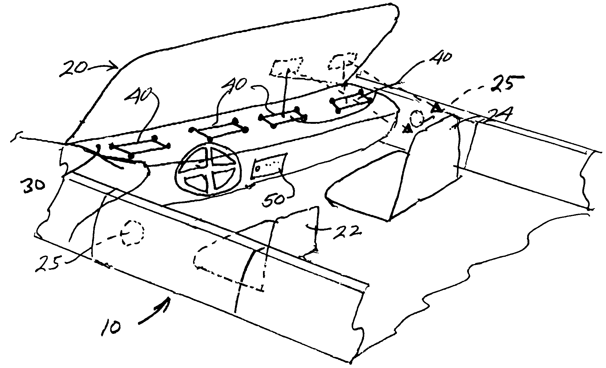
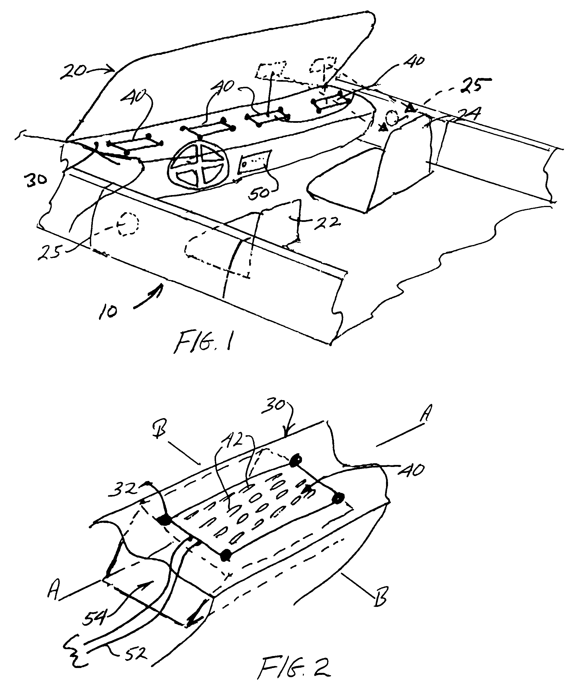
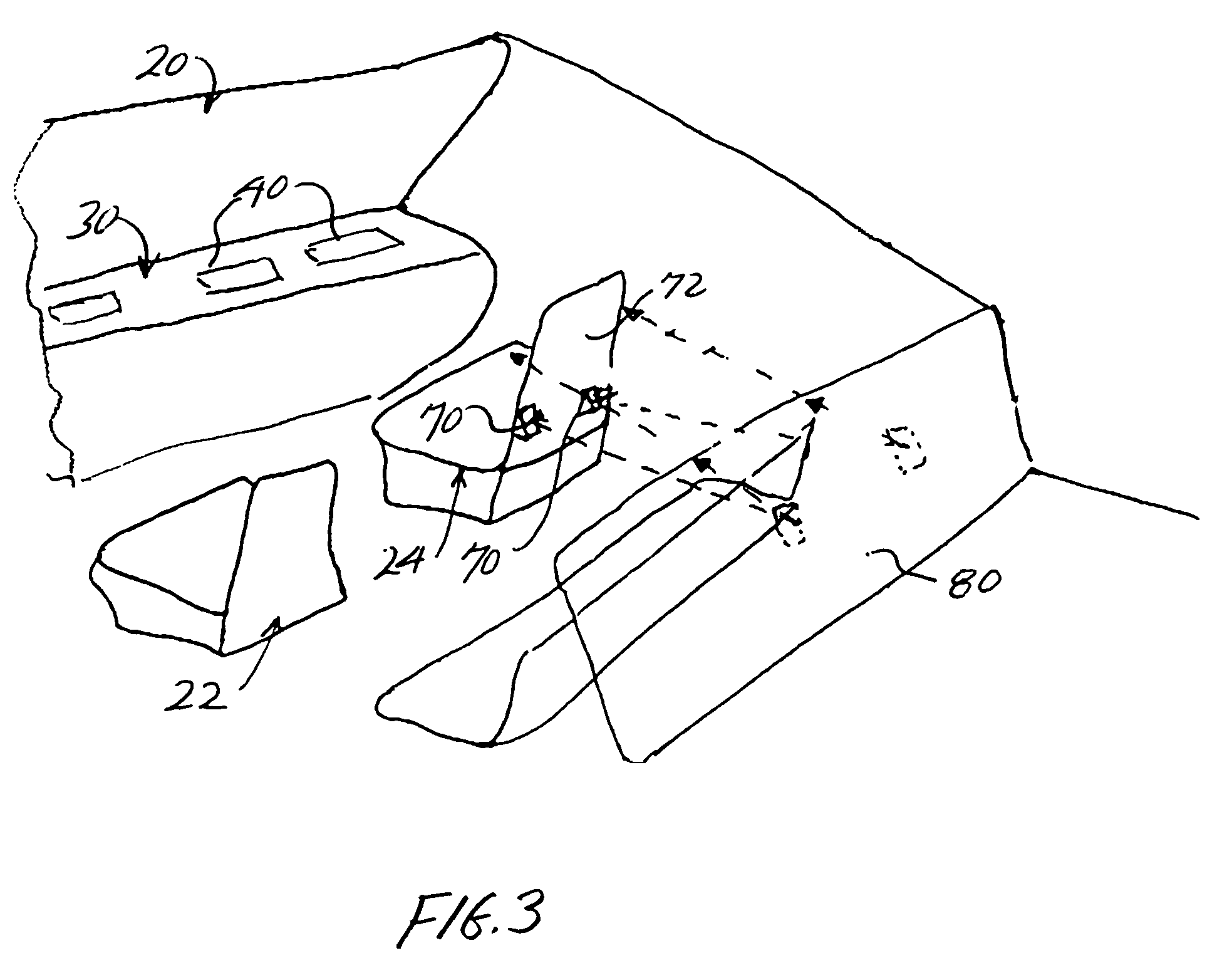
[0026]With particular reference to FIG. 1, an automotive vehicle 10, is shown having a windshield 20 and front dashboard 30. The windshield is typically angled towards the passenger seats, and slightly curved. As is typical in most vehicles, an audio source 50 is mounted along a front of the dashboard for easy access by passengers, and is electrically connected (not shown) to audio transducers to produce stereo sound. Directional acoustic transducers 40 are mounted as left and right pairs in holes or openings formed in the top surface of the front dashboard 30, using standard fasteners. Planar magnetic transducers are examples of transducers 40 providing required directionality at higher frequencies. Such transducers are often designed in rectangular shapes with...


PUM


Abstract

Automotive audio systems that use directional planar magnetic transducers in a layout or placement configuration to provide direct or reflected audio imaging in stereo or surround sounds for individual passengers of an automotive vehicle with reduced crossed audio interference.

Description

CROSS REFERENCE TO RELATED APPLICATIONS[0001]This application claims the benefit of U.S. Provisional Application Ser. No. 60 / 411,386, filed Sep. 18, 2002.BACKGROUND OF THE INVENTION[0002]1. Field of the Invention[0003]This invention is directed to the field of automotive sound systems of the type used in cars, trucks and the like and more particularly to direct and reflected sound imaging using planar magnetic transducers for the source of sound generation. The transducers are mounted and oriented within a vehicle such that separate stereo or surround sound stages are created for each passenger while cross talk or cross interference is reduced when compared with conventional sound systems.[0004]2. Description of the Related Art[0005]Conventional automotive speaker layouts use left and right transducers that are placed at opposite sides of an automotive vehicle. This results in unequal sound arrival amplitude and time cues such that there is little or no stereo image perceived by a p...

Claims


Application Information

Patent Timeline
IPC IPC(8): H04R5/02
CPCH04R5/02H04R2499/13
Inventor THIGPEN, F. BRUCE
Owner EMINENT TECHNOLOGY
Why Eureka
Eureka Blog
Learn More